03_SM481_Service Manual Installation.pdf - 第16页
Advance d High Speed Flex ible Mounter 3-12 2. Turning t he kno b of the reg u lator, a dj ust th e a ir p ressure to 0. 45 ~ 0.55 MPa. ( The a ir con sumption o f this m achine i s m ax. 300 N ℓ /mi n .) At this time , …
Transfer & Installation Procedure
3-11
3. Install the keyboard bracket on the upper front cover and install the keyboard, mouse, etc.
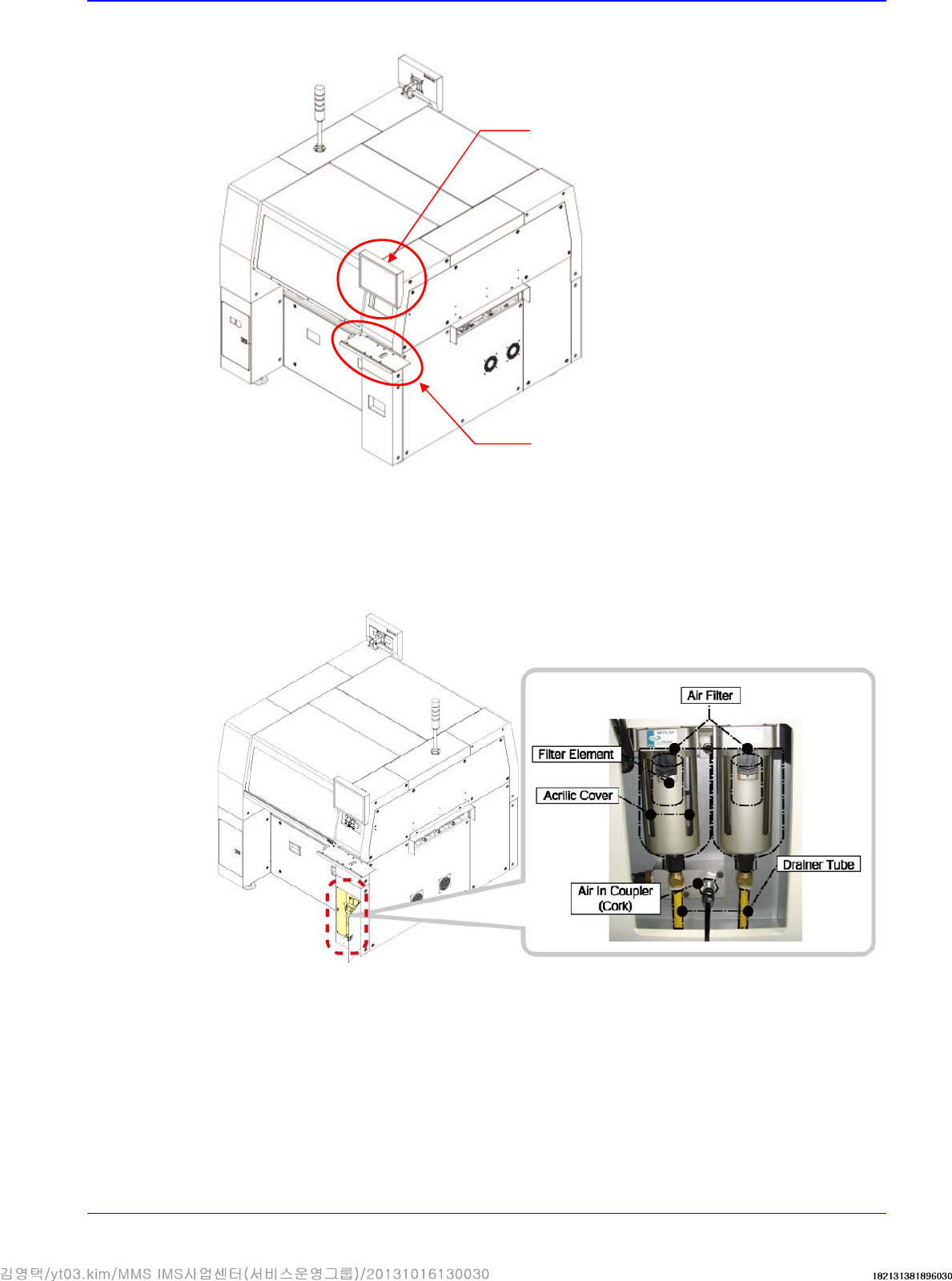
3.1.5. Pneumatic Pressure Setup and Cable Connection
1. Connect pneumatic hose to the left fitting of the air filter. At this time, Check if the air filter is
installed or not in the air main source device.
Monitor
Keyboard Stand
Advanced High Speed Flexible Mounter
3-12
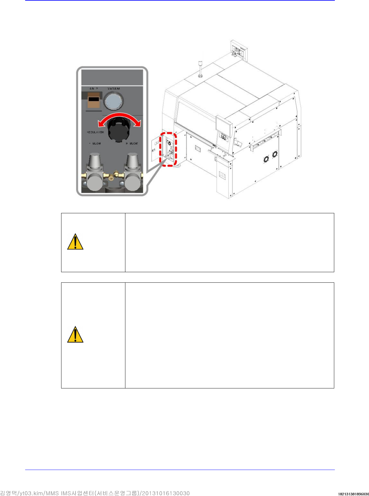
2. Turning the knob of the regulator, adjust the air pressure to 0.45 ~ 0.55 MPa. (The air
consumption of this machine is max. 300 Nℓ/min.) At this time, the outside diameter of the
pneumatic hose greater than 12mm is recommended.).
Caution
If the pneumatic pressure exceeds 0.45~0.55 Mpa, a problem may
occur in the part pickup and placement and feeder movement.
Therefore, check the pneumatic pressure before performing the
work. A compressor with appropriate capacity for the pneumatic
consumption of the machine must be used. Otherwise, the
reduction of the pneumatic pressure in the machine has influence
on the part placement quality.
Caution
Oil leakage into the pneumatic pipeline due to the compressor
being too old may cause fatal errors in each machine. Foreign
matters like chips and burs remain inside the pipe once piping
work is completed. Therefore, it is recommended to flush the
piping with the pipe ends being covered with a clean cloth. If the
cloth remains clean and there is no sign of contamination, after a
series of flushings,
then connect the pneumatic pipe to the machine. Check if the air
dryer has been installed to prevent moisture condensing inside the
pipe.
In order to prevent the oil inlet into the pipes and freezing to occur,
check if the oil filter and air dryer are installed.
Pressure increase
(clockwise)
Pressure
reduction
(counterclockwise)
Transfer & Installation Procedure
3-13
3.1.6. Power Connection
3.1.6.1. Power Connection Procedure
1. Check the temperature at the where the machine is installed using the temperature gauge.
(Recommended temperature: 24 ± 4°C)
Allowable range: +10°C ~ +35°C
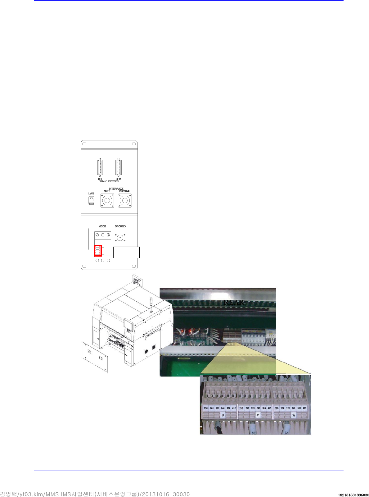
2. Check the the power supply voltage at the place where the machine is installed.
Ex) (tripple phase, 220V, option (tripple phase, 200, 208, 240, 380, 415V )
3. After checking the power supply to the place of machine installation, check if the measured
voltage is normal or not by using the digital multimeter. The default for power specification is
“3 phases AC 200±18V / 208±19V / 220±20V / 240±22V / 380±25V / 415±28V.
4. Unscrew the fixing screws (4 sets) of the panel at the rear bottom of the SM471 to remove the
cover, Then check the input voltage setup of the transformer. (Unless specified otherwise, the
SM411 is shipped with the power supply set to 3-phase and 220V.)
OFF
REAR
3 phases 20V