00194579-0202.pdf - 第38页
Retrofit instructions Wide board 242 / 508 mm SIPLACE HS-60 / D4 08/2006 Edition 40 2.5 Safety instructions W ARNIN G The safety instructio ns from the “Operational safety” chapte r of the user manual and servicing in- s…
Retrofit instructions Wide board 242 / 508 mm SIPLACE HS-60 / D4
08/2006 Edition
39
– Conveyor options: The extended conveyor cannot be modified if conveyor options are installed
on the PCB conveyor that prevent the stationary side wall being moved. Options or special de-
signs, such as ceramic substrate centering or vacuum tooling, which are permanently installed
on the lifting table, are not possible with 242 mm/508 mm conveyor widths.
PCB alignment and Long board are still supported.
2.3 Parts list: 119455 HS-60 / D4 242 mm/508 mm PCB
conveyor
2.4 Tools and consumables required
Set of hexagon socket spanners 2
The following mapping boards: 2
2 2x 2 00335609-01 2 Reflector 2
2 2x 2 00335672-01 2 DIN 6912-M8 x 10-8.8 2
2 1x 22Mount for limit switch LPT 242mm/508mm option 2
2 2x 22 DIN M4 x 10 2
2 2x 22DIN M4 2
2 4x 2 00366104-01 2 TR grease nipple DIN 3405-AM6 2
2 8x 2 00305531-01 2 DIN 913 - M 6 x 5-ST 2
2 1x 2 00377572-01 2 Component mapping board 520x380 HS-60/S-27HM 2
2 1x 2 00194579-01 2 Retrofit Instructions: Wide board 242 / 508 mm SIPLACE HS-60 2
00375916-xx 2 Mapping test board 520x380,
dual conveyor 2
HS-60 dual conveyor (242mm)
(mapping is only possible up to
380mm in single conveyor mode) 2
00373952-xx 2 Mapping test board HF/X 508x450 2 HS-60 single conveyor (508mm) 2
00377061-xx 2 Component mapping board 520x380
HS-60/S-27HM 2
HS-60 dual conveyor (242mm)
(mapping is only possible up to
380mm in single conveyor mode) 2
00377572-01 2 Component mapping board 508x380
HS-60/Wide 508
(included in the retrofit kit) 2
HS-60 single conveyor (508mm) 2

Retrofit instructions Wide board 242 / 508 mm SIPLACE HS-60 / D4
08/2006 Edition
40
2.5 Safety instructions
WARNING
The safety instructions from the “Operational safety” chapter of the user manual and servicing in-
structions take precedence over these instructions. 2
The SIPLACE placement machines are supplied with mains voltage.
Consequently parts of these systems carry dangerous voltages! This voltage is present at certain
modules inside the machine base, even when the machine is switched off at the main power
switch.
Incorrect handling of the placement machine or touching live parts of the machine can result in
death or severe injury, and considerable damage to equipment.
BEFORE starting any work, shut down the operating system correctly, then switch the machine
OFF at the main power switch and disconnect from the main power supply. In addition, the com-
pressed air supply must be switched off at the compressed air unit's main valve in the machine
base and vented by actuating the needle valve on the compressed air unit.
There is DANGER for heart pacemaker wearers in the vicinity of the linear motors, as described
in detail in the "Special safety instructions for working in the vicinity of strong magnetic fields"
section of the user manual and service manual.
Always follow the accident prevention regulations, DIN or other standards and special safety
rules applicable in your country.
Pay attention to the information concerning residual voltages in the Operational Safety chapter.
Follow the ESD regulations as described in the operational safety section of the operating
instructions.
During the retrofit, always secure the machine to prevent access by other people and to prevent
it being switched on again. The procedure is described in the “Locking the machine…” section of
the user manual.
Working with the SITEST program further increases the risk of accident.
The SITEST program must only be used by authorized and trained personnel.
2
2.5.1 Definitions
2
PLEASE NOTE 2
2
2
Retrofit instructions Wide board 242 / 508 mm SIPLACE HS-60 / D4
08/2006 Edition
41
2.6 Conversion
2
The conversion must only be carried out by SIPLACE service engineers. 2
2
2
2.6.1 Moving the machine zero point
To be able to set the conveyor on the HS-60 / D4machine type to its maximum conveyor width
(Wide), it is first necessary to move the machine zero point. The hardware must be converted by
a service engineer in order to do this. The following sequence should also be followed in order to
return the machine zero point to its previous default position. 2
2
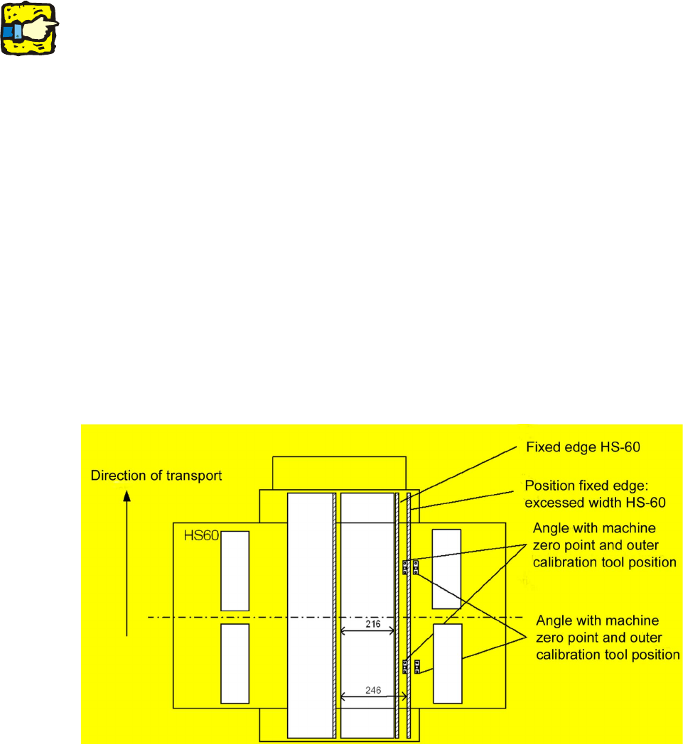
Description of the mechanical conversion for the machine zero point (picture) 2
2
There are already holes for moving the angle unit exactly 25 mm to the outside. Only two of the 4
screws have to be removed (the 2 screws marked with a red dot are for fitting and remain fixed).
Move the angle units and tighten the 2 screws. 2
2
Fig. 2.6 - 1 Illustration of the need to convert the hardware
2