00194579-0202.pdf - 第41页
Retrofit instructions Wide board 242 / 508 mm SIPLACE HS-60 / D4 08/2006 Edition 43 2.6.2 Removing reflect ors and grease nipples : Replace the existing reflector (item no.: 00335 609 -01) with the new reflector on gantr…
Retrofit instructions Wide board 242 / 508 mm SIPLACE HS-60 / D4
08/2006 Edition
42
2
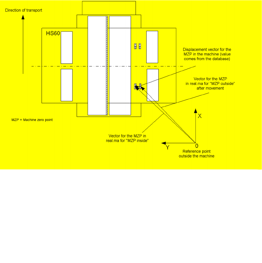
Fig. 2.6 - 2 Illustration of important vectors for moving the machine zero point
2
: Check the "Conveyor zero point" entry
in the C:\SrDaten\SrcMa
directory in the "real.ma" file:
The conveyor zero point should have the following value, depending on the software version:
Enter the correct value if this is not the case.
: Switch the placement machine off at the main switch.
The software changes take effect when the machine is switched on again.
2
2
2
2
2
2
from version 505.03 onwards M18 674080
for older versions 671580
Retrofit instructions Wide board 242 / 508 mm SIPLACE HS-60 / D4
08/2006 Edition
43
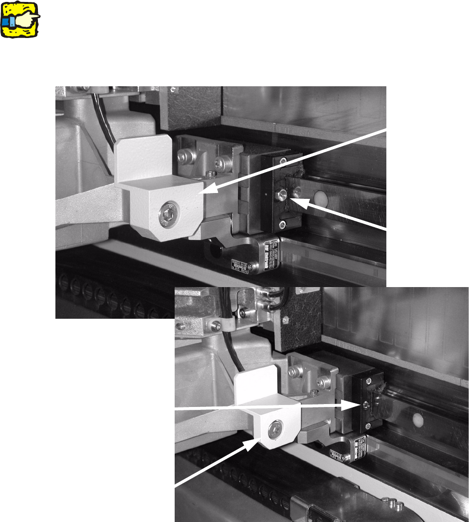
2.6.2 Removing reflectors and grease nipples
: Replace the existing reflector (item no.: 00335609-01) with the new reflector on gantries 2 and
4.
2
Do NOT use reflectors with the same item number, but release -02 (00335609-02). 2
2
: Replace the installed grease nipples on the insides of all the gantries (2 screws on each) with
the grub screws (DIN 913 - M 6 x 5-ST, item no.: 00305531-01).
2
2
With
grease nipple
Without
grease nipple
Remove old
reflector
(FS -02)
Fit new reflector (FS -01)

Retrofit instructions Wide board 242 / 508 mm SIPLACE HS-60 / D4
08/2006 Edition
44
: Switch the placement machine on at the main switch.
2
When the reflectors are removed, the safety distance of the gantries for the gantry synchronization
must be reduced. This must be done by the line engineer using the "MaDatenEditor“ utility. 2
The settings depend on the software version: 2
From version 505.03 onwards M21:
The reduced gantry distance is calculated by the software if the machine zero point was moved
outwards. 2
2
If the value can also be reduced manually, then the gantries may move too closely together. 2
2
For older versions: 2
: In the table entitled "Determining the travel range for the Y axis", change the values for "iMin-
PortalAbstand“ from 180000 to 176000 or from –180000 to –176000.
2
2
2
2
2
2
2
2
2
2
2
2
2
2
2
2
2
2
2