00196845-02_AI_Vakuumpumpe_SXDX4_X-Serie-S_de_en.pdf - 第109页
Fitting the Vacuum Pump 3.2.20 Conversion for C&P20a Changeover Vacuum Pump Vakuumpumpe 109 3.2.20.3 3 . 2 . 2 0 . 3 F it t in g t h e A p e r t u r e R in g a n d V a c u u m C o v e r Fitting the Aperture Ring and …
Fitting the Vacuum Pump
Changeover 3.2.20 Conversion for C&P20a
108 Vacuum Pump Vakuumpumpe
3.2.20.1
3.2.20.1 Removing the Silencer
Removing the Silencer
3.2.20.2
3.2.20.2 Removing the Vacuum Unit Holding Circuit C&P20A
Removing the Vacuum Unit Holding Circuit C&P20A
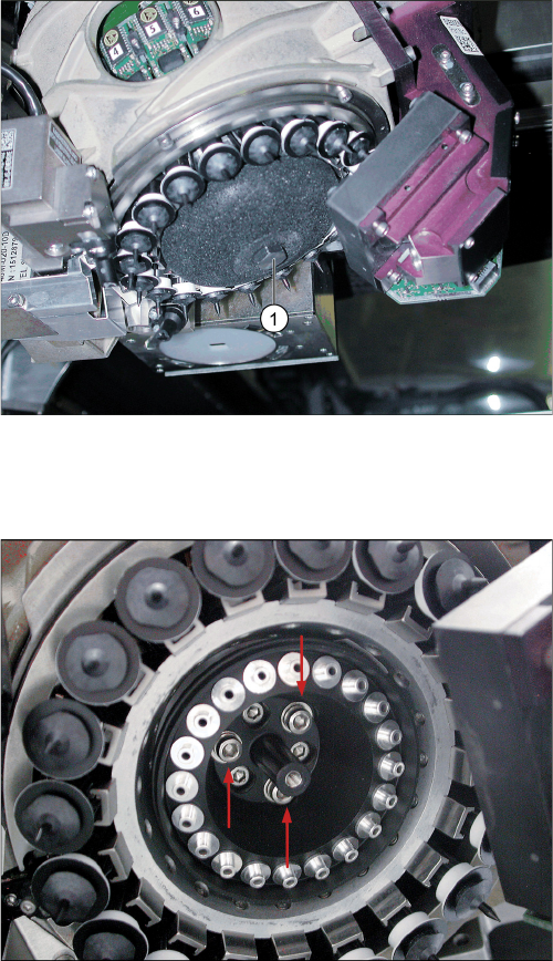
C&P20A with porous silencer for compressed air
► Make sure that you do not damage or contaminate
the camera lens system.
► Loosen the screw (1) fastening the silencer.
► Carefully lever out the silencer.
► Make sure that you do not damage the DP drives.
C&P20A with vacuum unit holding circuit
► Unscrew the three screws and remove the vacuum
unit holding circuit for the C&P20.
Fitting the Vacuum Pump
3.2.20 Conversion for C&P20a Changeover
Vacuum Pump Vakuumpumpe 109
3.2.20.3
3.2.20.3 Fitting the Aperture Ring and Vacuum Cover
Fitting the Aperture Ring and Vacuum Cover
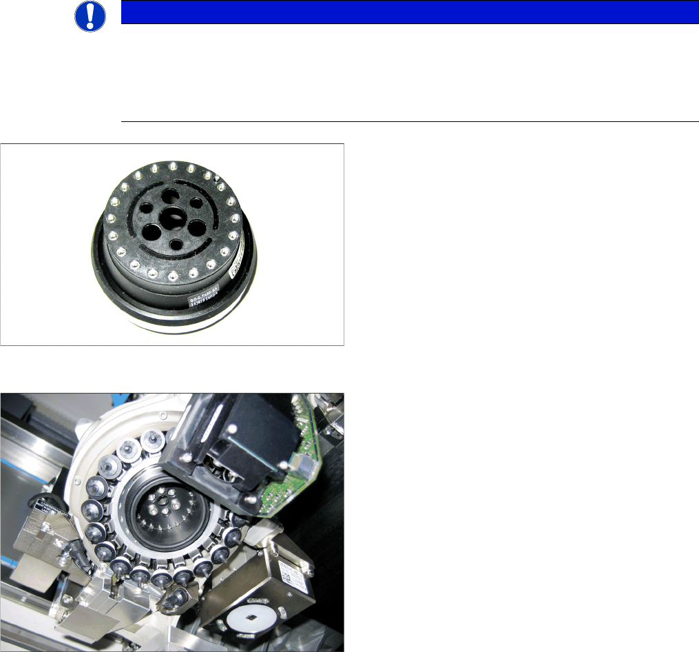
NOTICE
Aperture ring
Before inserting the aperture ring, make sure that the seal disk [03046345-xx] has been posi-
tioned correctly (orientation) on the aperture ring for the C&P20A [03046344-xx].
When inserting the new aperture ring for the C&P20A, make sure that the pin engages in the
relevant hole on the star carrier. The aperture ring should remain fixed from alone.
Aperture ring C&P20A with seal disk
► When tightening the screws, carefully take hold of the
star near the segment guidances and hold it on the
star carrier.
► Make sure you do not damage the aperture ring or
nozzles.
C&P20 A with aperture ring C&P20 A [03046344
-
xx]
► Screw the aperture ring tight using the DIN912-
M3x10 screws. Make sure that it is not distorted.
► Check whether the O-ring 42x2 NBR70 has been
properly placed into the groove on the aperture ring.
Fitting the Vacuum Pump
Changeover 3.2.21 Final Work:
110 Vacuum Pump Vakuumpumpe
3.2.21
3.2.21 Final Work:
Final Work:
3.2.21.1
3.2.21.1 Docking the Component Trolley (SX Machines)
Docking the Component Trolley (SX Machines)
► Fit the empty tape duct and fix into place with four screws, inserted from below and attached to the
assembly brackets on the left and right.
► Dock the component trolleys into place.
3.2.21.2
3.2.21.2 Fitting the Manual Table (DX Machines)
Fitting the Manual Table (DX Machines)
3.2.21.3
3.2.21.3 Switching the Machine On
Switching the Machine On
► Open the compressed air shut-off valve.
► Close all doors.
► Switch the machine on at the main switch.
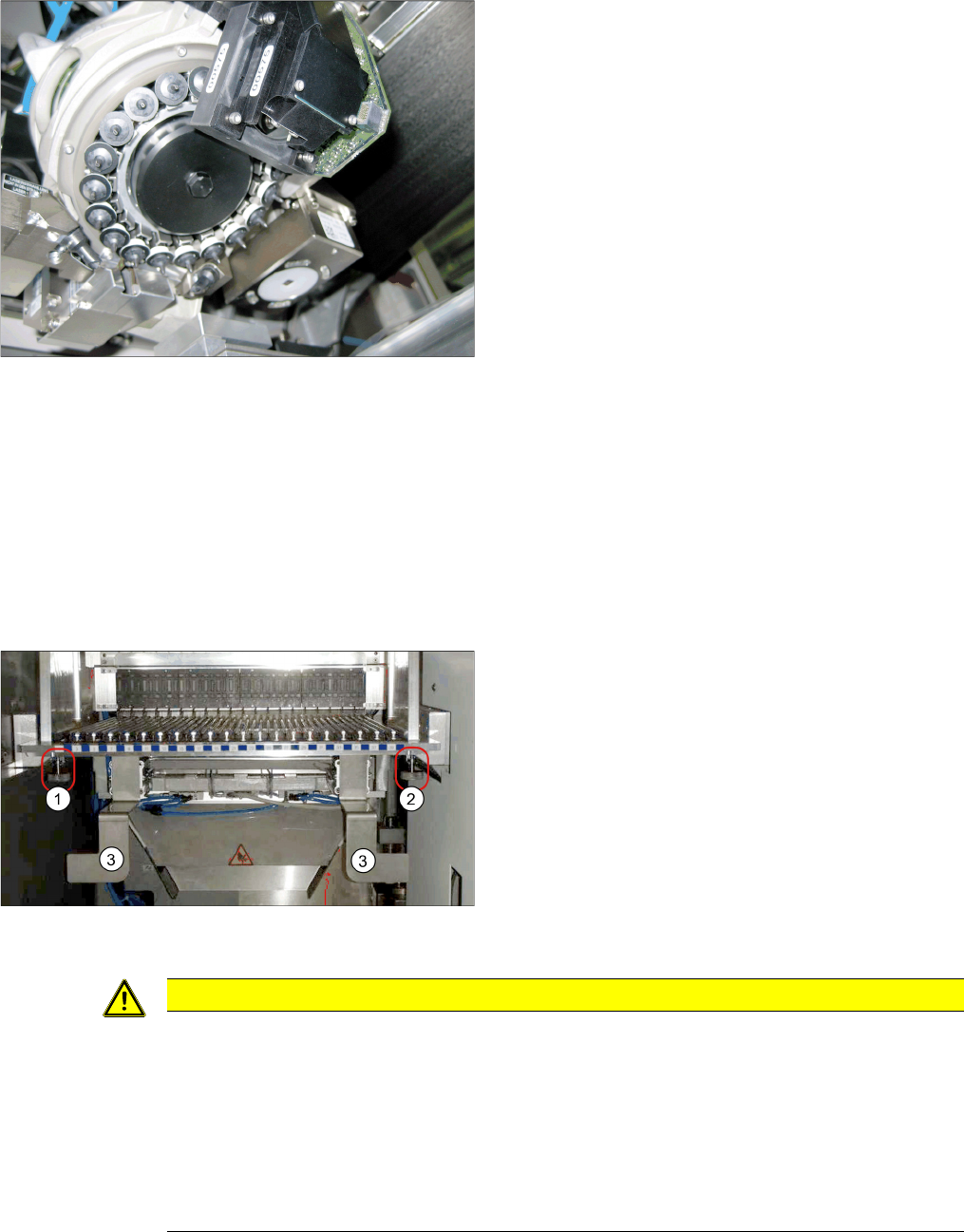
C&P20A with vacuum cover
► Screw the cover [03046347-xx] hand-tight onto the
aperture ring C&P20A.
► Fit the empty tape duct and fix into place with four
screws, inserted from below and attached to the as-
sembly brackets on the left and right (3).
► Insert the table into the machine and fix it into place
with the two knurled screws underneath the table (1
and 2).
► Insert the tape container and the reject tray.
CAUTION
Switch-on preconditions
Before switching on, perform the following checks to prevent injuries or serious damage to
property:
Make sure of the following before you switch the compressed air supply back on:
► Check that all hose connections are correctly assigned (also that there is no compressed
air in the vacuum hose).
► Check that all conditions for switch-on of the vacuum pump and connected placement ma-
chine have been fulfilled, as specified in the user guide.