00196845-02_AI_Vakuumpumpe_SXDX4_X-Serie-S_de_en.pdf - 第69页
Introduction 1.1.1 Conventions for the use of safety instructions Safety Instructions Vacuum Pump Vakuumpumpe 69 1 1 I n t r o d u c t io n Introduction This manua l describes t he i nstallation of the Be cker VX4 25 [0 …
Anhang
Auszüge aus der Serviceanleitung 5.6.1 Motorschutzschalter/Motorschutz-Auslöserblock tauschen
68 Vacuum Pump Vakuumpumpe
Ausbau
► Schalten Sie die Maschine aus, trennen Sie diese vom Stromversorgungsnetz und sichern Sie die
Maschine gegen Wiedereinschalten. Beachten Sie dazu Abschnitt "1.2 Was vor Beginn der Arbeiten
zu tun ist..." [ ➙ 10].
► Lösen Sie alle Verbindungen zum Motorschutzschalter. Markieren Sie sich ggf. deren Position, um
diese später wieder eindeutig zuordnen zu können.
Einbau
► Verfahren Sie für den Einbau in umgekehrter Reihenfolge. Beachten Sie dabei folgende Hinweise:
Einstellungen
► Stellen Sie die Auslöseschwelle für den Nennstrom ein (linke Einstellscheibe).
► Stellen Sie die Auslöseschwelle für die Überlastklasse ein (rechte Einstellscheibe).
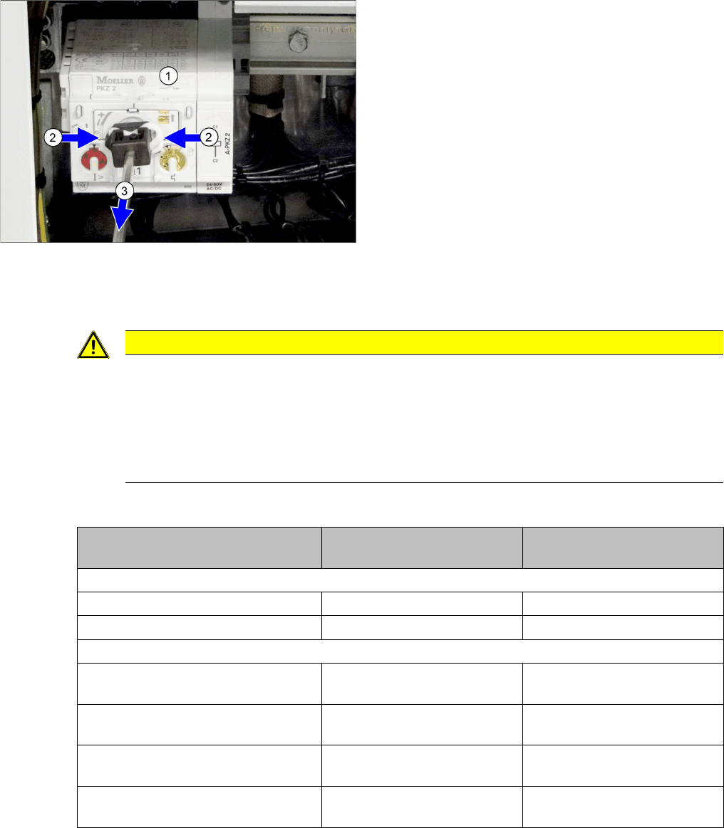
► Entfernen Sie die Welle, welche den
Motorschutzschalter (1) mit dem äußeren Haupt-
schaltergriff verbindet. Drücken Sie dazu die weißen
Kunststoffklammern zusammen (2) und ziehen Sie
die Welle ab (3).
► Lösen Sie die Verriegelung des Motorschutzschal-
ters auf der Schiene und nehmen Sie den Motor-
schutzschalter ab. Lesen Sie dazu ggf. die
beiliegende Herstelleranleitung.
VORSICHT
Einbauhinweise
► Beachten Sie unbedingt die Hinweise für eine korrekte Montage in der technische Informa-
tion "Nachrüstanleitung Achsstütze Motorschutzschalter PKE32/XTU-32 komplett 3p.
(Hauptschalter)" [DE: TI2013-07D10] [EN: TI2013-07E10].
► Bauen Sie die Welle vom alten auf den neuen Schalter um.
► Stellen Sie Nennstrom und Überstrom ein (s. u.).
Motorschutz Auslöseblock
PKE-ZTU-32
linke Einstellscheibe
für Nennstrom
rechte Einstellscheibe
für Überstrom Klasse
SX1/SX2
3x380V - 3x 415V 8A 5
3x200V - 3x230V 13,5A 5
X-Serie S, SX4/DX4
3x380V bis 3x415V
Keine oder eine Vakuumpumpe
8A 5
3x200V - 3x230V
Keine oder eine Vakuumpumpe
13,5A 5
3x380V bis 3x415V
Zwei Vakuumpumpen
13,5A 5
3x200V bis 3x230V
Zwei Vakuumpumpen
17,2A 5

Introduction
1.1.1 Conventions for the use of safety instructions Safety Instructions
Vacuum Pump Vakuumpumpe 69
1
1 Introduction
Introduction
This manual describes the installation of the Becker VX4 25 [03069679-xx] vacuum pump for C&P20 A
heads at SIPLACE® machines if type X-Series S, SX4 and DX4.
1.1
1.1 Safety Instructions
Safety Instructions
1.1.1
1.1.1 Conventions for the use of safety instructions
Conventions for the use of safety instructions
This manual contains notes that must be observed to guarantee your personal safety and to avoid dam-
age to equipment. These notes are highlighted by warning triangles and are indicated as follows accord-
ing to the level of risk:
DANGER
Nonobservance of these safety instructions may cause injury to personnel and damage to the
machine!
► Please observe the safety instructions in the user manual of the relevant machine for all
work!
DANGER
Definition
For the purposes of this manual, this indicates that fatal or severe injuries or considerable dam-
age to property will occur if this hazard warning is not observed.
WARNING
Definition
For the purposes of this manual, this indicates that fatal or severe injuries or considerable dam-
age to equipment may occur if these warning instructions are not followed.
CAUTION
Definition
For the purposes of this manual, this indicates that minor injuries or damage to property may
occur if this caution is not observed.
NOTICE
Definition
For the purposes of this manual, this note provides information about the product or indicates
a part of the manual that requires particular attention.

Introduction
Safety Instructions 1.1.2 Safety Instructions for Working with Strong Magnetic Fields
70 Vacuum Pump Vakuumpumpe
1.1.2
1.1.2 Safety Instructions for Working with Strong Magnetic Fields
Safety Instructions for Working with Strong Magnetic Fields
1.1.3
1.1.3 Safety Instructions for the Power Supply
Safety Instructions for the Power Supply
▪ This means that some parts of the system carry potentially lethal voltages - even when switched off
at the main power switch.
▪ Incorrect handling of the placement system can therefore result in fatal injuries, severe injuries or
considerable damage to equipment.
▪ Measurements and maintenance work must always be carried out by appropriately qualified person-
nel.
▪ Always follow the applicable accident prevention and DIN regulations (particularly DIN EN 60 204,
part 1) or the regulations specific to your country.
▪ Before starting any maintenance work, switch the machine off at the main switch and disconnect it
from the main power supply.
▪ Always secure the machine against unauthorized reactivation. If these instructions are not followed,
you may be able to touch live parts, which could result in fatal or severe injuries.
Maintaining, Installing or Removing Assemblies
► End all placement operations on the machine.
► Shut down the Windows operating system correctly, otherwise problems may occur when restarting
or data may be lost.
► Switch the machine off at the main switch.
► Disconnect the machine from the main power supply.
► Switch off the machine and attach warnings signs to indicate that service work is in progress.
DANGER
Strong permanent magnet fields
Fatal hazard: persons with active implants (e.g. pacemakers, defibrillators, insulin pumps etc.)
are at risk from strong permanent magnetic fields inside the machine.
Persons at risk should avoid the immediate vicinity of the machine.
CAUTION
Danger of crushing
Danger of crushing for persons with passive metal implants (e.g. plates, screws).
► Do not reach or lean over into the machine when the protective covers are open.
► Do not bring any metal objects into the hazard area.
CAUTION
Strong permanent magnet fields
There is a risk that the strong magnetic fields could corrupt data on data media or check cards.
► Keep sensitive data supports away from the permanent magnets.
WARNING
Hazardous Voltages!
The machine is supplied with 3 x 400 V~ (or. 3 x 204 V~ / 3 x 220 V~ / 3 x 230 V~ / 3 x 380 V~
/ 3 x 415 V~) ± 5 %, 50/60 Hz mains voltages.
► Observe the safety instructions in the user manual during all service work!