00196845-02_AI_Vakuumpumpe_SXDX4_X-Serie-S_de_en.pdf - 第87页
Fitting the Vacuum Pump Pneumatic and Vacuum Supply Vacuum Pump Vakuumpumpe 87 3 3 F it t in g t h e V a c u u m P u m p Fitting the Vacuum Pump 3.1 3 . 1 P n e u m a t ic a n d V a c u u m S u p p ly Pneumatic and Vacuu…

Brief description
Vacuum Pump - Special Features 2.3.6 Fan sheet [03101019-xx]
86 Vacuum Pump Vakuumpumpe
2.7
2.7 Vacuum Pump - Special Features
Vacuum Pump - Special Features
The vacuum pump is switched on and off with the machine. The software automatically takes into ac-
count a stopping time of 6 minutes on switch-off, to prevent the motor overheating from the inrush current
peaks.
2.8
2.8 C&P20A Placement Head - Special Features
C&P20 A Placement Head - Special Features
An SX-Series vacuum pump [03069679-xx] can supply a maximum of two C&P20 A heads.
When retrofitting the vacuum pump option, the venturi vacuum generator for the C&P20 A head ("vacu-
um unit hold circuit C&P20“) is replaced with the "reflecting ring assembly C&P20" [03046348-xx]. Only
the hold circuit is supplied directly by the vacuum pump.
Irrespective of this, the pressure control valve and the return cylinder are still supplied with compressed
air in the pickup and place positions.
The "vacuum consumption" of the placement machine depends only on the number of placement heads
and the size of the nozzles. The more C&P20 A heads are connected to the vacuum pump, the lower
the vacuum level will be at the nozzles.
When the placement operation begins, the vacuum increases with each component picked up. An aver-
age vacuum value will soon form, based on the number of nozzles closed at the same time (with picked
up components) and number of nozzles open (components placed).
In SX4/DX4 machines, two of four heads are blocked by components when in placement mode.
NOTICE
Maximum of 2 C&P20 A heads
This vacuum pump can supply a maximum of two C&P20 A heads. If using an SX4 with four
C&P20 A heads, you therefore need two vacuum pumps. These vacuum pumps are fitted at
locations 1 and 4, behind the COT inserts in the machine base.
NOTICE
Retrofit each machine separately
The vacuum pump is connected to the power supply for the placement machine and can there-
fore only be operated when the machine is switched on. When a line is converted to vacuum
operation, each machine in the line therefore needs to have its own vacuum pump.
NOTICE
Observe the warnings
Always observe the additional service instructions for the vacuum pump.
► Read section "4 Maintenance" [ ➙ 113] and the service manual for your machine.
Fitting the Vacuum Pump
Pneumatic and Vacuum Supply
Vacuum Pump Vakuumpumpe 87
3
3 Fitting the Vacuum Pump
Fitting the Vacuum Pump
3.1
3.1 Pneumatic and Vacuum Supply
Pneumatic and Vacuum Supply
The following diagram shows conversion of a machine with two C&P20A heads to vacuum pump oper-
ation.
A maximum of two C&P20A heads can be connected to one vacuum pump.
Preconditions (according to machine configuration) see "2.8 C&P20A Placement Head - Special Fea-
tures" [ ➙ 86].
The machine monitors when the vacuum pump is switched on and off (e.g. after longer production stand-
still times).
CAUTION
Safety instructions and manufacturer's instructions
In addition to the safety instructions in the introductory chapter, the manufacturer's safety in-
structions, installation and setup instructions apply to the vacuum pump and must be observed.
Avoid switching the placement machine and vacuum pump on and off multiple times within a
short period. This can have a negative influence on the service life of the pump.
The placement machine monitors when the vacuum pump is switched on and off e.g. after long-
er production standstill times.
CAUTION
Compressed air
Never turn the compressed air on during the conversion, as this could lead to the placement
head being irreparably damaged, depending on the installation status.
CAUTION
TwinHead and CPP
When using a TwinHead or CPP placement head, never convert the pneumatic supply, gantry
distributor or trailing cable! If you do, there is no guaranty that the TwinHead or CPP will function
properly.
CAUTION
Switching the machine on and off
Avoid switching the machine and vacuum pump on and off multiple times within a short period.
This can have a negative influence on the service life of the pump.
Fitting the Vacuum Pump
Changeover 3.2.1 Switching off the Machine
88 Vacuum Pump Vakuumpumpe
3.2
3.2 Changeover
Changeover
DX4 machines are fitted with a manual table as a default. The component trolley is an option.
SX4 machines are fitted with component trolleys.
Before installing the pump, make sure that locations 1, 2 and 4 are accessible.
► Undock the component trolleys from the relevant locations of the SX4 machines.
Or
► Remove the manual tables from the relevant locations of the DX4 machines (see "3.2.2 Removing
the Manual Table (DX Machines Only)" [ ➙ 88]).
3.2.1
3.2.1 Switching off the Machine
Switching off the Machine
► Shut down the station computer and switch off the machine at the main switch.
► Disconnect the machine from the main power and the pneumatic supplies.
► Always secure the machine against unauthorized reactivation. See "1.2 Preparatory Work..." [➙72].
3.2.2
3.2.2 Removing the Manual Table (DX Machines Only)
Removing the Manual Table (DX Machines Only)
► Take out the tape container and the reject tray.
3.2.3
3.2.3 Dismantling the Waste Slide
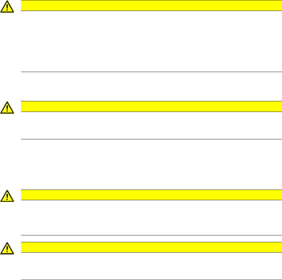
Dismantling the Waste Slide
► Loosen the two knurled screws underneath the table
(1 and 2) and lift the table out of the machine.
► Remove the two brackets (3) for the tape container
from the manual table.
Waste slide (example of DX4 shown)
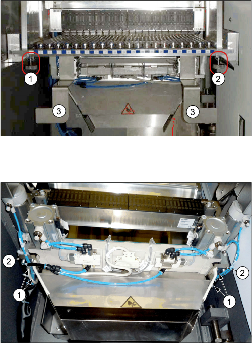
The following tasks must be performed at the manual ta-
ble and at the component trolley:
► Loosen the four screws (1) fastening the waste slide
from below to the assembly brackets (2), on the left
and right, and remove the waste slide.