Portal_Manual_1.2.1_Rev_H-1.pdf - 第42页
Portal PVA Revisio n H ( 2018 ) 42 of 93 8.4 Needle C alibrat ion The workcell has one of thr ee calibration methods: Standard, Ope rator Def i ned, and Sensor Defined. If a sensor d efine d or o pe rat or d efined met h…
Portal
PVA
Revision H (2018)
41 of 93
8. Weigh the dispensed quantity of material in grams. Subtract the weight of the
cup if necessary.
9. Find the volume in cc with the equation below:
Grams of material/specific gravity=cc
Ex: .500g/.96=.5208cc
10. Use this value (in cc) to find the correct number of counts per cc dispensed.
Counts/cc= counts per cc
Ex: 25counts/.5208cc= 48.003 counts per cc
11. Do this procedure at least three times and average the results.
12. Open the Main Program in a text editor such as Windows NotePad.
13. Search for the variable: FCA_CAL= It will be in the section titled: REM !!!!
Machine-Specific Information!!!!
14. Type in the new value for FCA_CAL= (Ex: FCA_CAL=48.003)
15. Download the modified main program and test changes.
Flow Monitor
Variables
A
DEZ FCA_CAL
B
DEW FCB_CAL
C
DEE FCC_CAL
D
DEF FCD_CAL
Table 1: Flow Monitor Variables
Portal
PVA
Revision H (2018)
42 of 93
8.4 Needle Calibration
The workcell has one of three calibration methods: Standard, Operator Defined, and
Sensor Defined. If a sensor defined or operator defined method is installed on the
workcell, the machine may or may not automatically enter its particular calibration
mode when you enter Auto mode. This will depend on the application the workcell was
set up for. Refer to Sections 8.4.1-8.4.3 for information on different calibration
sequences.
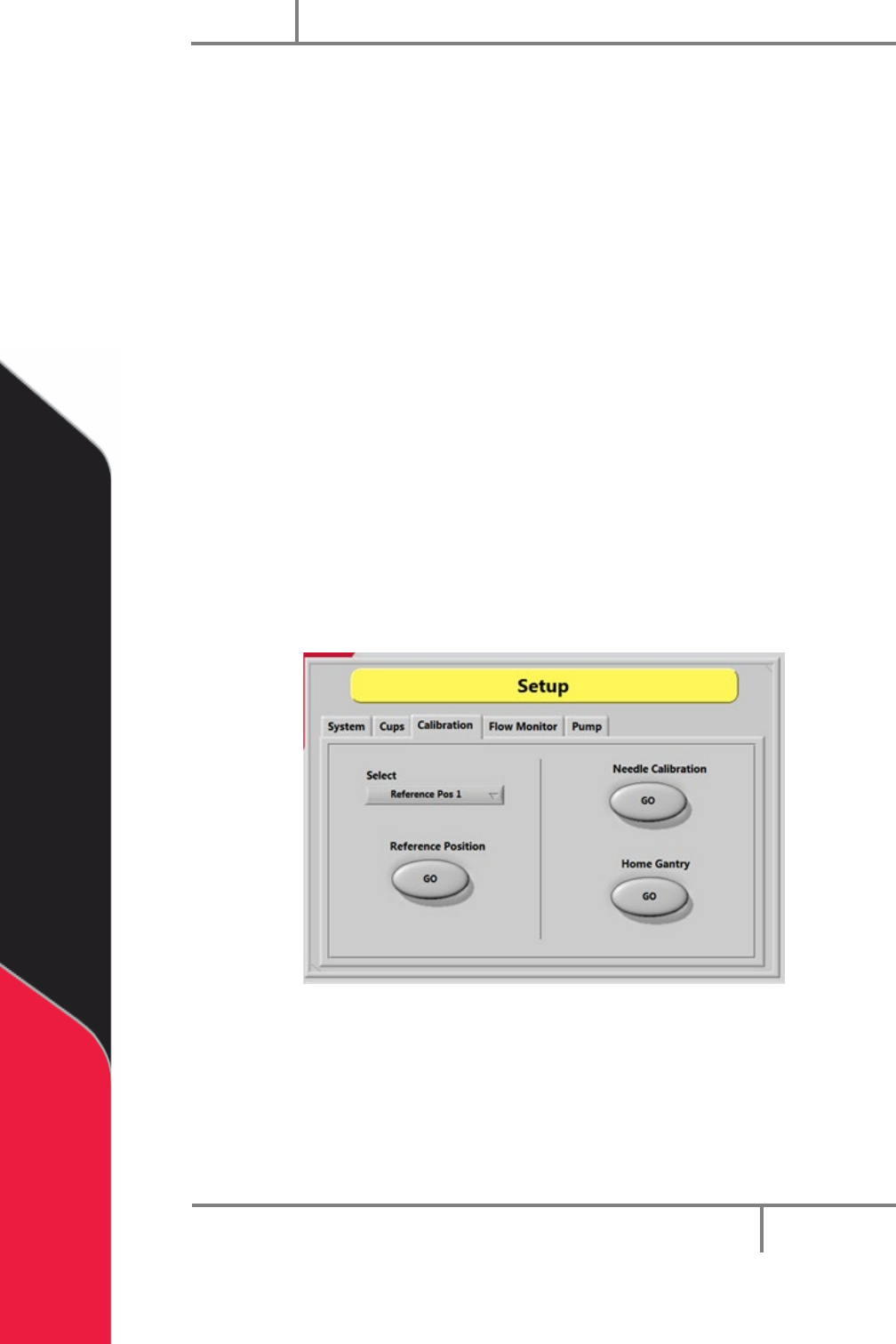
8.4.1 Standard Needle Calibration
Standard needle calibration is the easiest calibration procedure.
1. Select the “Calibration” tab in Setup mode.
2. Select the necessary valve or tool from the drop down “Select” menu.
3. Select the Reference Position “GO” button. The selected valve will move to the
calibration point.
4. Examine the position of the needle as it relates to the calibration point (such as
cross-hairs).
5. If the needle is not directly above the point, use your hands to bend the needle
or adjust the tool position so the needle is above the calibration point.
Figure 28: Needle Calibration
Portal
PVA
Revision H (2018)
43 of 93
8.4.2 Operator Defined Needle Calibration
For operator defined needle calibration you must use the trackball to define the
coordinate system to the position of a specific needle or dispense head. If the needle is
in the correct position, this procedure is not necessary.
1. The head moves to a calibration point (specified in the main program).
2. When at the calibration position use the trackball to put the needle tip in
correct position as it relates to a calibration point (such as cross-hairs).
3. Select the “CAL” function key to start this procedure if a needle needs to be
replaced during operation.
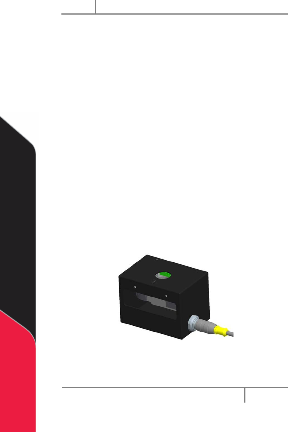
8.4.3 Sensor Defined Needle Calibration
The Needle Calibration Unit (NCU) is referenced from the home position on the gantry.
The start positions for each head to enter the NCU are referenced from the cross-hair
mark on the top of the NCU. The coordinates are defined for each head using thru-beam
sensors in the NCU.
• Z is always calibrated first in a downward motion into the Z sensor.
• The X and Y coordinates are then calibrated from this position in reference to
the positioning of the NCU in the work area. The needle moves into the next
sensor (X or Y) finding the first coordinate, then moves to the opposite side of
the sensor and finds a second coordinate.
• The calibration routine then calculates the center of the needle average of the
first and second coordinates and redefines the new position accordingly. This
sequence is repeated for the remaining axis.
Figure 29: Needle Sensor Calibration Block