Portal_Manual_1.2.1_Rev_H-1.pdf - 第51页
Portal PVA Revisio n H ( 2018 ) 51 of 93 10.1.1 Portal Shell 7. Make sure the comp uter related to the workcell is on. Portal Shell will o pen and give yo u a list of o ptions. 8. Select “ Launch Port al ”. Fig ure 41 : …
Portal
PVA
Revision H (2018)
50 of 93
10 Operation
NOTE: You must have administrator privileges to setup and correctly configure
the workcell. Windows
®
User Account Control must be turned off.
10.1 Startup Procedure
NOTE: Do not power on the workcell, or add material to the pressure vessels
until they are correctly grounded.
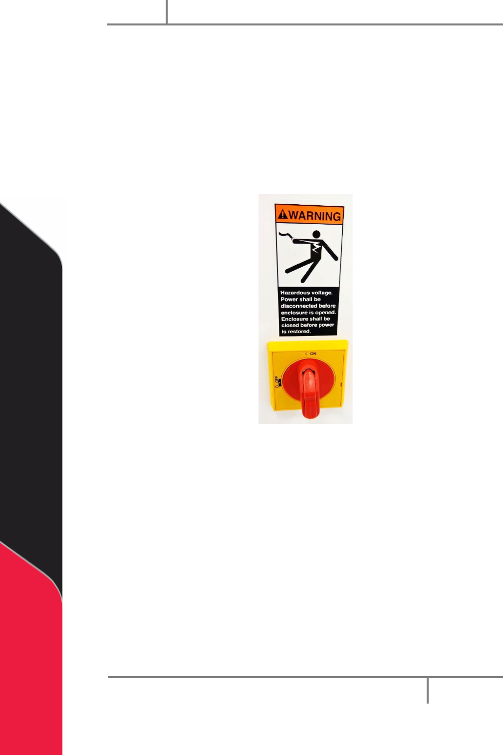
1. Turn the main power switch “On”.
Figure 40: Example of a Main Power Switch
2. Make sure the fluid and air pressures are in the correct pressure range.
3. Close all the doors.
4. Turn the DOOR BYPASS key switch to the “OFF” position (If applicable).
5. Engage the “Emergency Stop” button.
6. Turn the main power switch to the “On” position.
Portal
PVA
Revision H (2018)
51 of 93
10.1.1 Portal Shell
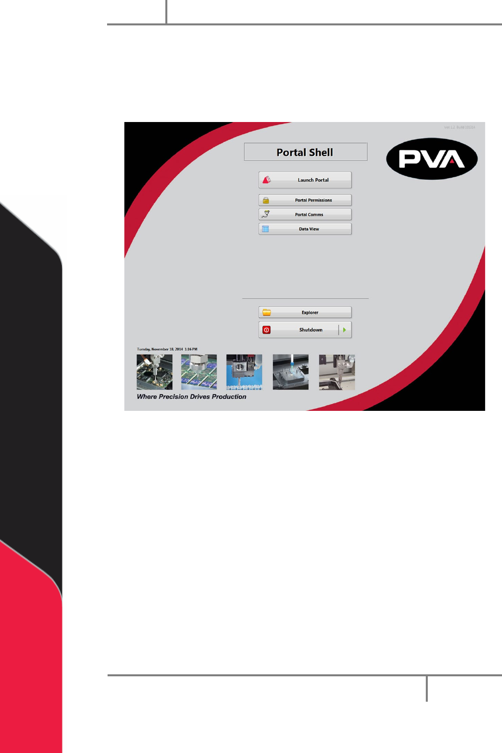
7. Make sure the computer related to the workcell is on.
Portal Shell will open and give you a list of options.
8. Select “Launch Portal”.
Figure 41: Portal Shell
Portal
PVA
Revision H (2018)
52 of 93
10.1.2 Login to Portal
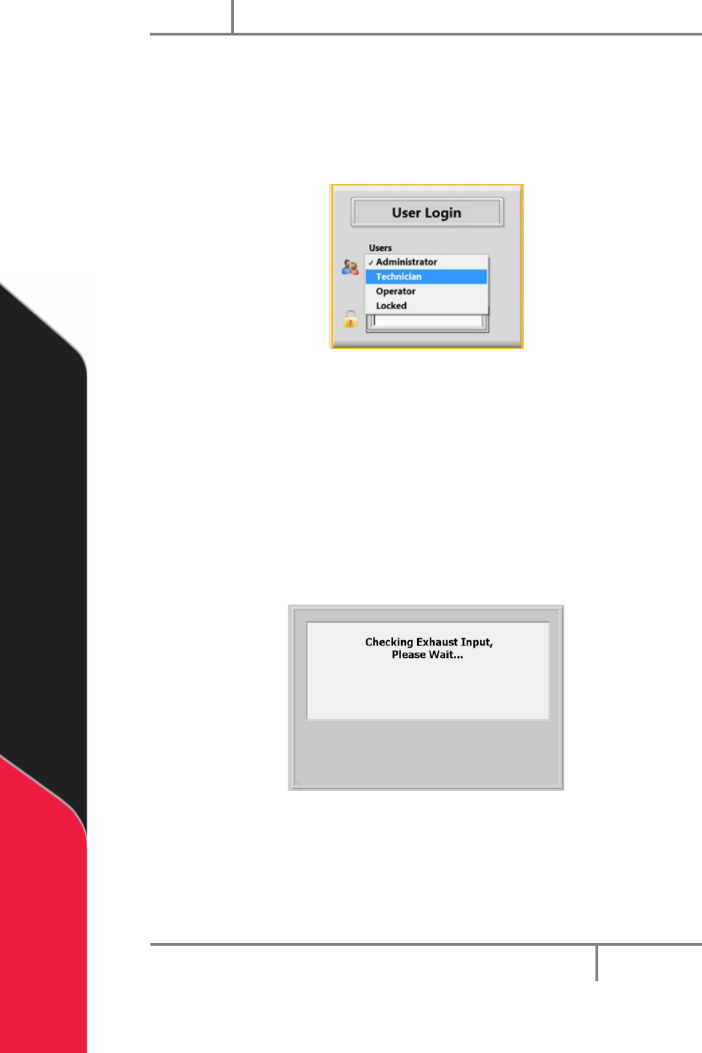
9. Login to the PVA Portal Software. Select the correct user and enter the
password. Push the “Enter” button on the keyboard.
10. PVA configures the default password as blank. Refer to portal permissions for
more information.
Figure 42: User Selection
10.2 Exhaust Verification
Once the workcell has initialized, it will do a test of the exhaust flow rate. If initialization
fails, refer to your workcell manual for fault diagnostics. The exhaust flow rate is
monitored with the on board pressure differential switch.
The workcell must exhaust at a rate no less than 300 cubic feet per minute (CFM),
otherwise a critical fault will occur and stop the motors. The test will also help to
evacuate any vapors that are in the work area. The time this takes is based on the CFM
and the area that must be evacuated. The screen below will be shown:
Figure 43: Exhaust Input Screen