Portal_Manual_1.2.1_Rev_H-1.pdf - 第54页
Portal PVA Revisio n H ( 2018 ) 54 of 93 10.4 Homin g the Axe s After the safety ch eck is complete , th e screen bel ow is shown. Fig ure 46 : Home the System 1. Select “ Continue ” to h ome the syst em. 2. The axes h o…
Portal
PVA
Revision H (2018)
53 of 93
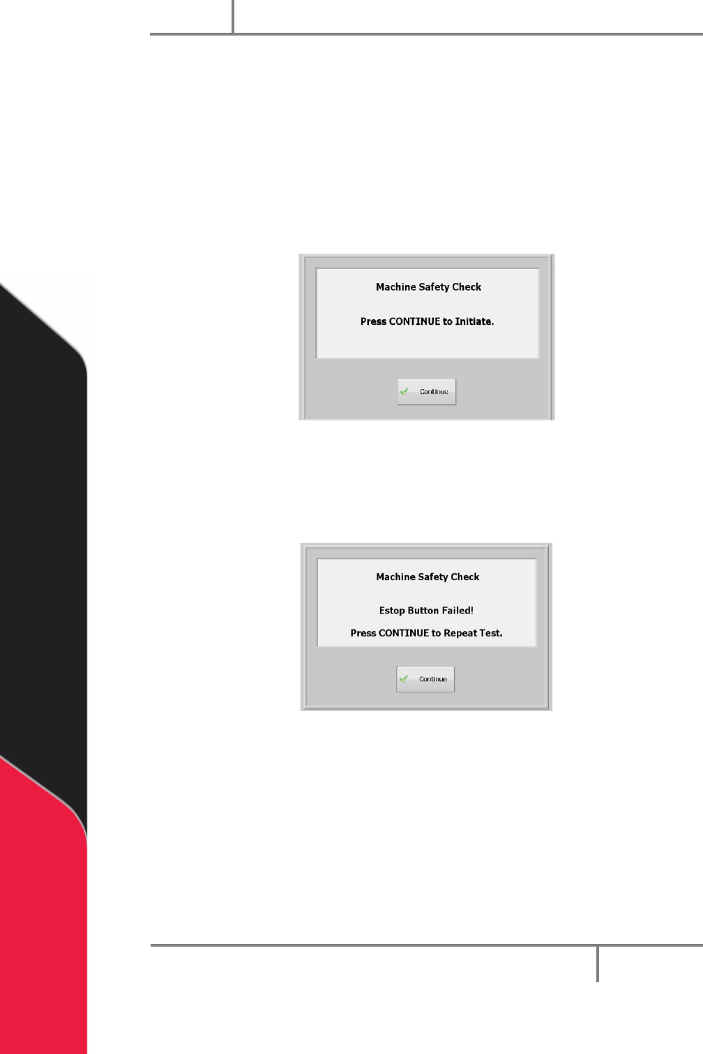
10.3 Machine Safety Check
Once initialization and exhaust verification is complete, the operator interface shows
the message below
The machine safety check makes sure the workcell safety devices (Emergency Stop, door
interlocks, light curtain, etc.) operate correctly. During startup, the operator must start
the safety check and complete it successfully, or the machine stops all operations.
1. Select “Continue”.
Figure 44: Machine Safety Check
2. You must activate and deactivate the safety devices when shown on the screen.
All events in this procedure are timed. If an action is not done in 8 seconds an
error screen will be shown.
Figure 45: Safety Check, EStop Fail
3. Select “Continue” to repeat the test.
After the second failure, the workcell stops and must be restarted (turn the workcell
power off and on again). The second failure does not have to be for the same device. An
Emergency Stop failure followed by a door interlock failure stops the program.
NOTE: If the safety check fails, a qualified person must examine the full system
before the machine is operated again. Refer to the Troubleshooting Power
Check Failures Document.
Portal
PVA
Revision H (2018)
54 of 93
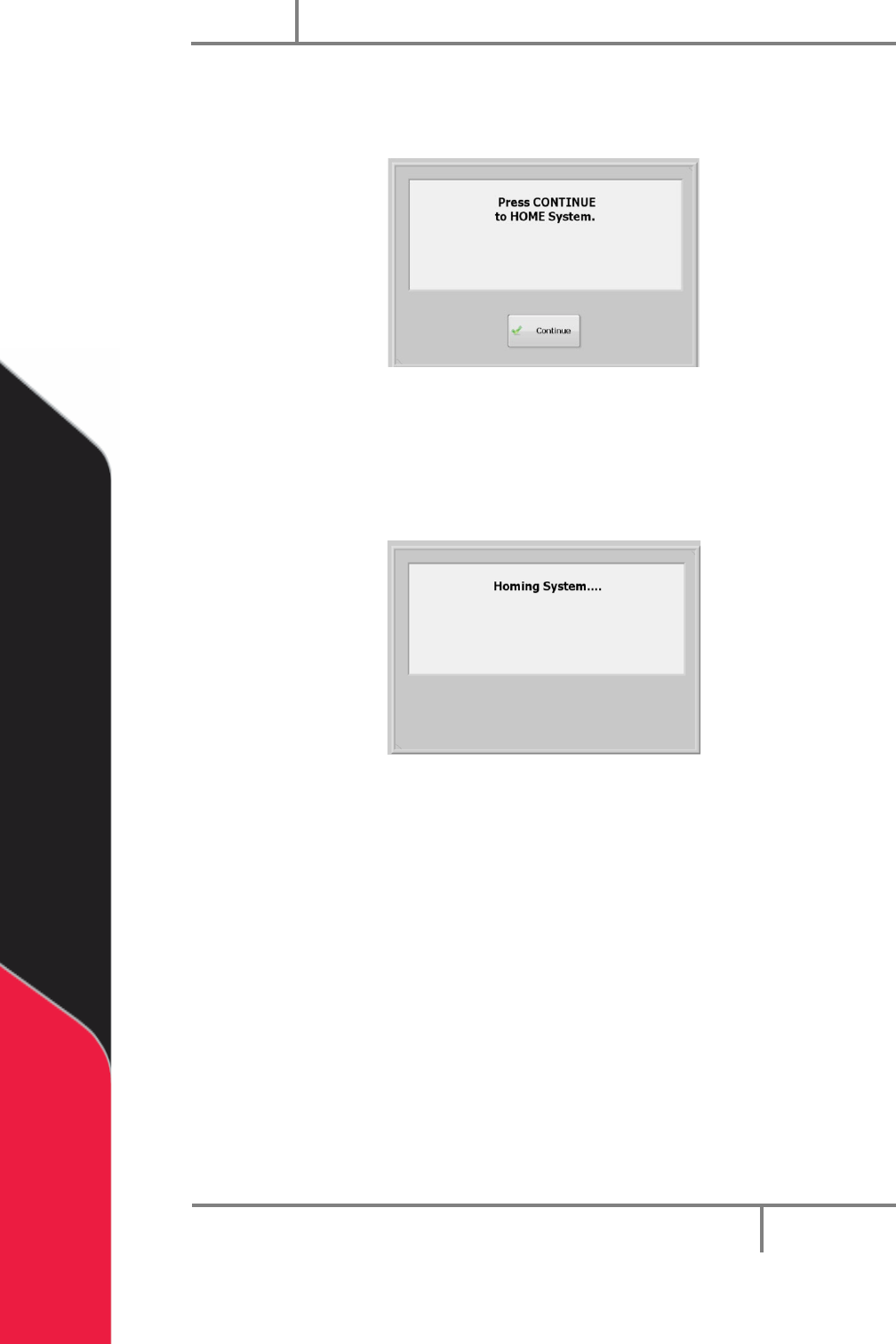
10.4 Homing the Axes
After the safety check is complete, the screen below is shown.
Figure 46: Home the System
1. Select “Continue” to home the system.
2. The axes home in the following order: Z, W (if installed), then X & Y
simultaneously.
Figure 47: System Homing Screen
Portal
PVA
Revision H (2018)
55 of 93
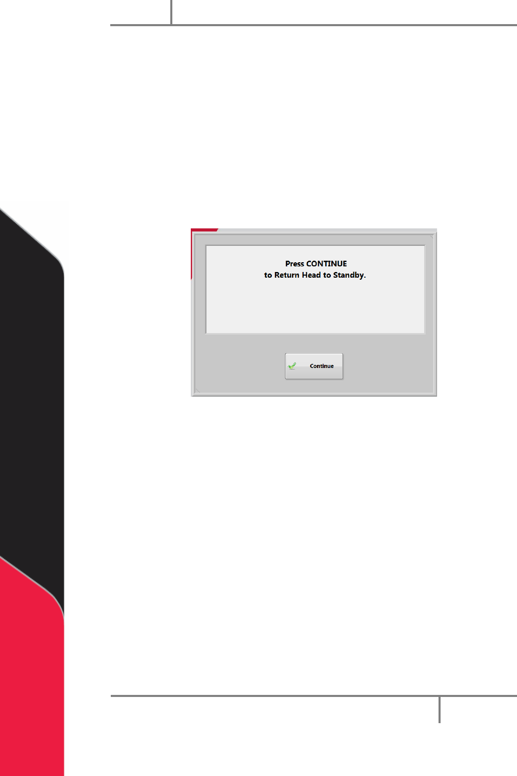
10.5 Standby Position
The end effector will move to the standby position when the homing sequence is
complete, all calibration procedures are complete, a part is finished being processed, or
if the machine is waiting for parts but it is not necessary to move to solvent or auto
purge. The standby position is a defined location, different from the home position.
Usually, the standby position is near the board stop to decrease travel during Auto
Cycle. The workcell always goes back to the standby position in Cycle Stop. If the
standby position needs to be changed, contact PVA.
1. When Portal opens select “Continue” to return the heads to standby and go to
cycle stop mode.
Figure 48: Press Continue Portal Screen
10.6 Solvent Cups
Some workcells have solvent cups installed. When solvent cups are used, the auto purge
feature is overridden by the solvent cup routine. The Setup mode setting for frequency
has no effect but after the device leaves the solvent cups the purge duration is used.
The solvent cup location is different for each workcell but will be in the workcell
workspace. Solvent cups are used to keep the dispense/spray heads clean, if necessary.
• In Cycle Stop, the heads are in the solvent cups.
• In Manual mode, the heads will not go to the solvent cups until you exit Manual
mode.
• In Auto Cycle, the heads do the purge routine automatically. They return to the
solvent cups after a set period of inactivity.
To change the time delay before the heads enter the solvent cups in Auto Cycle, change
the value in the Sleep field under the “Cups” tab in Setup mode, refer to Section 8.2.