CP43维护手册.pdf.pdf - 第47页
5 – 5 V ersion 6.0 Chapter 5 The T welve Stations 7) Insert the gage into gap A at this point, loosen the nut and use the adjustment rod to eliminate any clearance between the roller and the gage. Fig. 5-4 Station 1 Feed…
Chapter 5 The Twelve Stations
• Adjustment Method
Have the special jig and gage prepared beforehand.
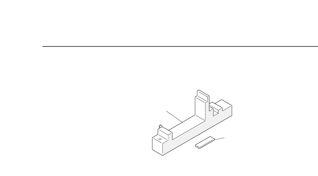
Fig. 5-3 Station 1 Adjustment Jig
Note : This jig is also necessary for the tape-positioning claw
adjustment (Section 5.1.2), push-up pin adjustment (Section
5.1.3), and for the tape-end detection adjustments (Section
5.1.4).
1) Set the adjustment jig at D1 on the device table.
• Ensure that there are no obstructions on the base of the jig.
• Confirm that the jig will not interfere with station 1.
Note: It is possible to make the adjustments with the jig set at
positions other than D1.
2) Press [SET] → [POSITION] → [D AXIS] → (input device # 1) →
[CR] and [START] to move the adjustment jig to station 1.
3) Press the EMERGENCY STOP button to take the machine from
200 volts down to 100 volts.
4) Watch the cam graduation plate and rotate the cam to 0° with
the cam handle.
5) Press [SET] → [MANUAL] → [I/O] → [OUT] (use the +Page
and the s t keys to select “Y020 Pickup Sol ON”) and then
change the display from X to O with [ON/OFF] to release the
station 1 solenoid stopper.
• If the solenoid is not released, the adjustment cannot be
performed.
6) Use the cam handle to rotate the cam to 260°.
• The roller pushes the feeding lever to the advance-limit feeding
position when the cam is at 260°.
Adjustment jig
Gage
5 – 4
Version 6.0
CP IV-3 Maintenance
5 – 5
Version 6.0
Chapter 5 The Twelve Stations
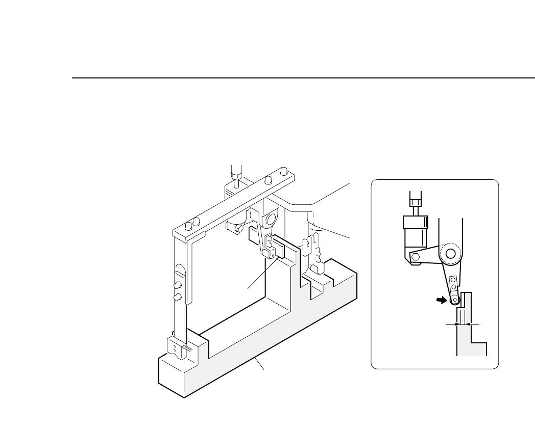
7) Insert the gage into gap A at this point, loosen the nut and use
the adjustment rod to eliminate any clearance between the
roller and the gage.
Fig. 5-4 Station 1 Feed Lever Adjustment (Cam at 260°)
Clearance A
= Gage thickness
Gage
Adjustment jig
CP IV-3 Maintenance
Chapter 5 The Twelve Stations
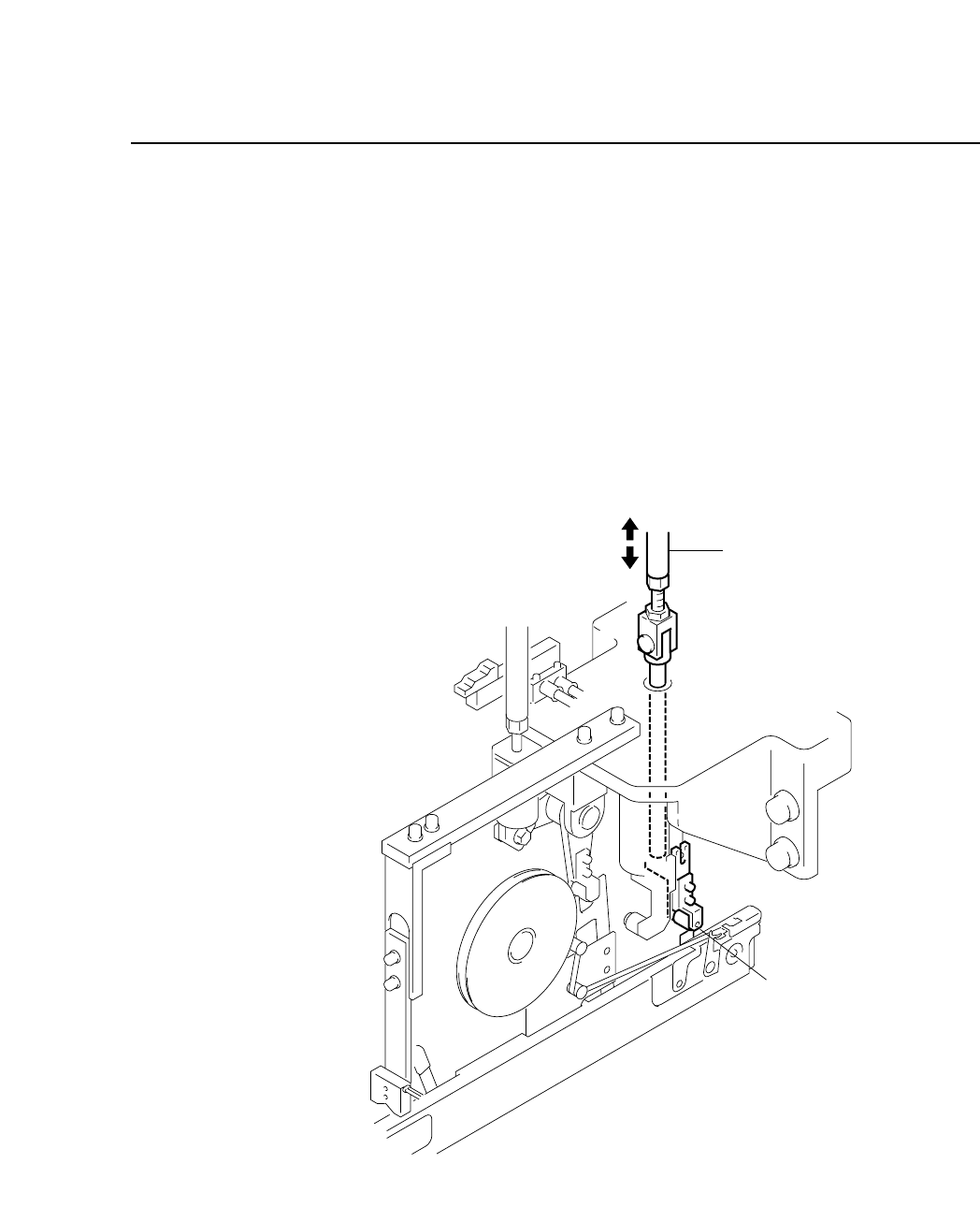
5.1.2 Tape Positioning Claw Vertical Stroke (16, 24, 32 mm and LPC
type feeders only)
The vertical tape mechanism moves the tape positioning cogs in the
feed holes of the tape set on the feeder. This mechanism raises the
positioning cogs into the feed holes and the tape-feed lever
advances the tape forward. The vertical movement of the
positioning cogs alone cannot advance the tape.
• Drive Mechanism
The cam starts the tape feed cycle by advancing the lever on the
feeder. The stroke (fixed) depends on the cam curvature.
Fig. 5-5 Station 1 Tape Positioning Claw
Adjustment rod
Roller
5 – 6
Version 6.0
CP IV-3 Maintenance