CP43维护手册.pdf.pdf - 第84页
Chapter 5 The T welve Stations T able 5-1 Amp Settings for Nozzle Pre-switch Check S L M Green unlit Green lit Green lit Green lit Green lit Green unlit Nozzle Sensor 1 Sensor 2 5 – 42 V ersion 6.0 CP IV -3 Maintenance
5 – 41
Version 6.0
Chapter 5 The Twelve Stations
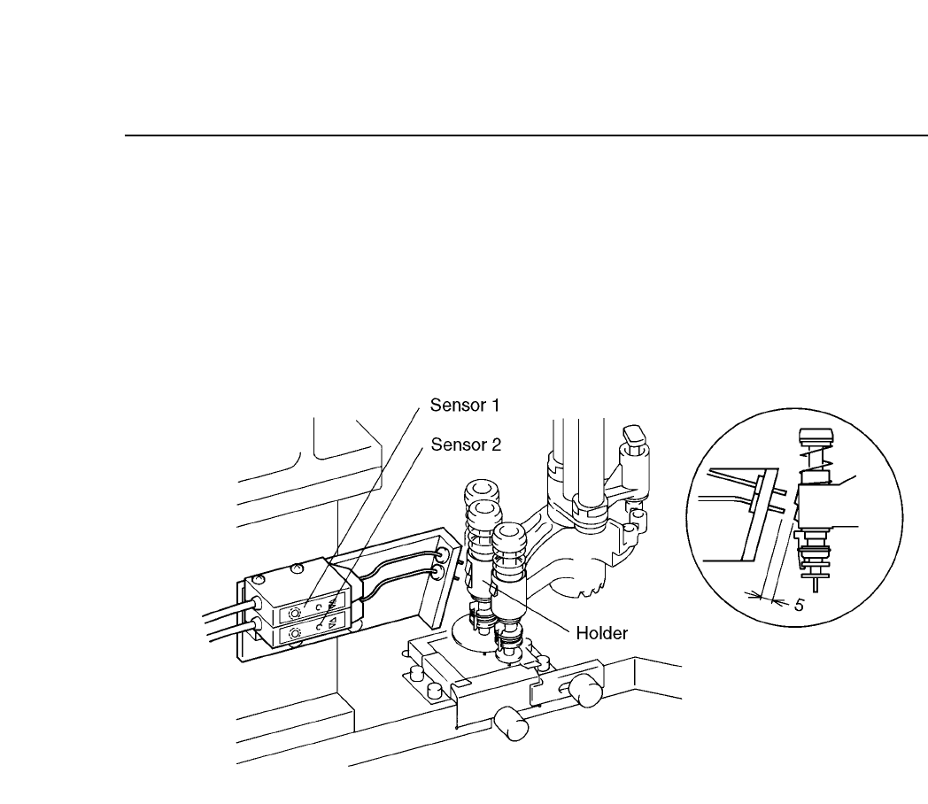
5.10.2Nozzle Pre-switch Check
Before nozzle change is carried out at station 11, the nozzle position
is checked. This check, called the nozzle pre-switch check, uses two
sensors to detect the position of the S, M, L nozzles. Because this
check is performed, no problems arise if the nozzle position is
changed by the operator at a station before station 10.
Fig. 5-45 Nozzle Pre-switch Check Mechanism
Follow the procedure below to adjust the nozzle pre-switch check
sensors.
(1) Set the cam angle to 0° and select the L nozzle. The S and M
nozzles cannot be adjusted. If the L nozzle is not selected,
remove the Station 8 holder, select the L nozzle, then re-attach
the holder and rotate the unit forward to station 10.
(2) Set the cam angle to 235° and adjust the sensor attachment
bracket so that the distance between the nozzle change sensor
tip and the holder is 5 mm as seen from the side ( see figure 5-
47).
(3) Line up the center (looking from above) of the nozzle change
sensor and the holder (see figure 5-47).
(4) Adjust the amplifier volume. Set the "on" position of sensors 1
and 2 to the point where the LED changes from red to green,
and then set the volume to the next higher mark on the dial.
CP IV-3 Maintenance

Chapter 5 The Twelve Stations
Table 5-1 Amp Settings for Nozzle Pre-switch Check
S
L
M
Green unlit
Green lit
Green lit
Green lit
Green lit
Green unlit
Nozzle Sensor 1
Sensor 2
5 – 42
Version 6.0
CP IV-3 Maintenance
5 – 43
Version 6.0
Chapter 5 The Twelve Stations
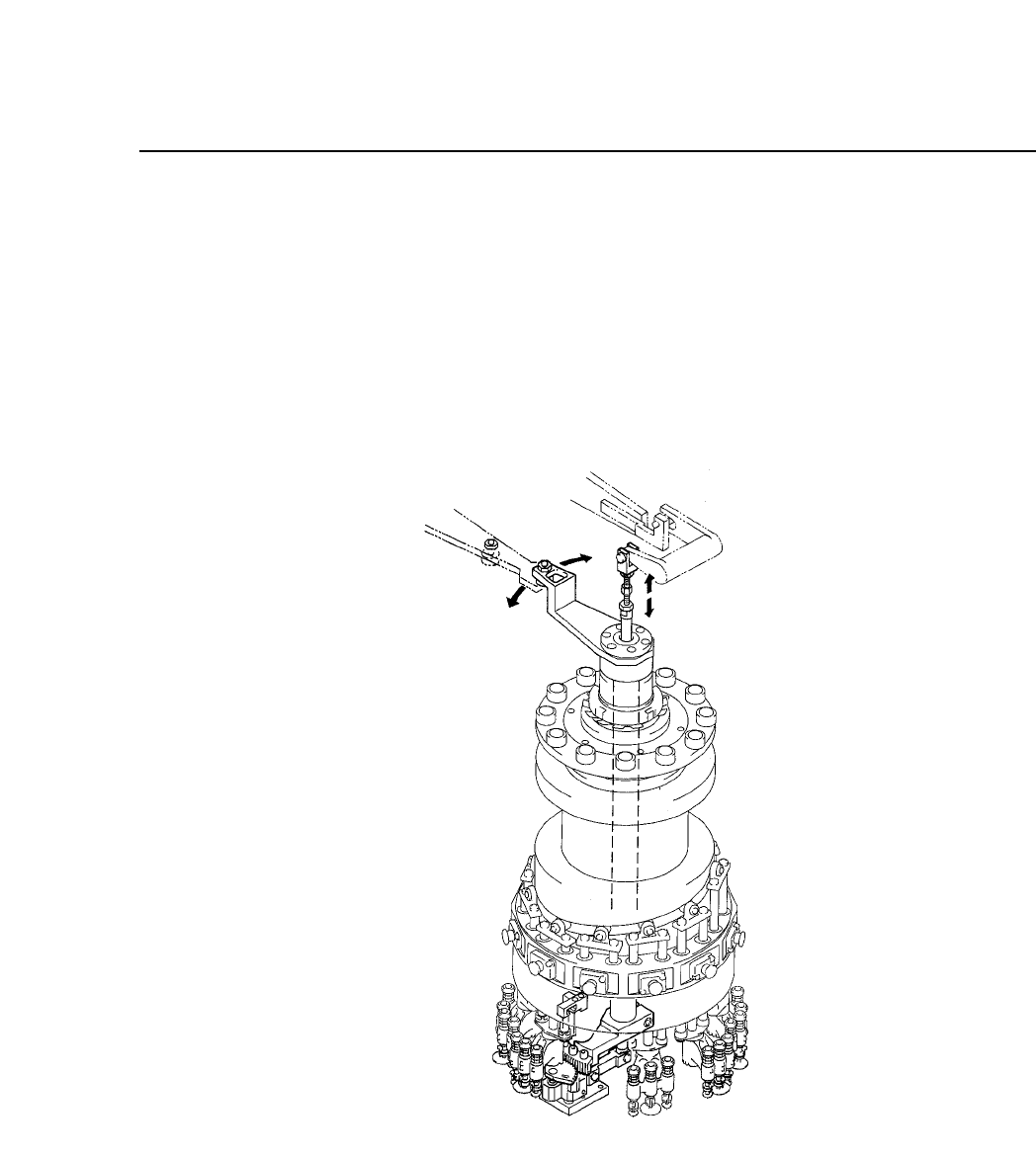
5.11 Station 11
At station 11, nozzle switching is carried out. The nozzle is selected using
Part dat and the data from station 10's pre-switch check.
The nozzle switch operation is driven by a cam mechanism. The cam
drives a lever, which drives a shaft, which drives a lever, which drives the
holder. This sequence of drive transmission combines with the action of
the cylinder.
Fig. 5-46 Nozzle Switch Mechanism at Station 11
Adjustment requires a special jig.
CP IV-3 Maintenance