CP43维护手册.pdf.pdf - 第86页
Chapter 5 The T welve Stations 5.12 Station 12 5.12.1 Nozzle Switch Check The nozzle switch check checks whether or not the nozzle has been correctly switched. If the nozzle has not been corr ectly switched, the machine …
5 – 43
Version 6.0
Chapter 5 The Twelve Stations
5.11 Station 11
At station 11, nozzle switching is carried out. The nozzle is selected using
Part dat and the data from station 10's pre-switch check.
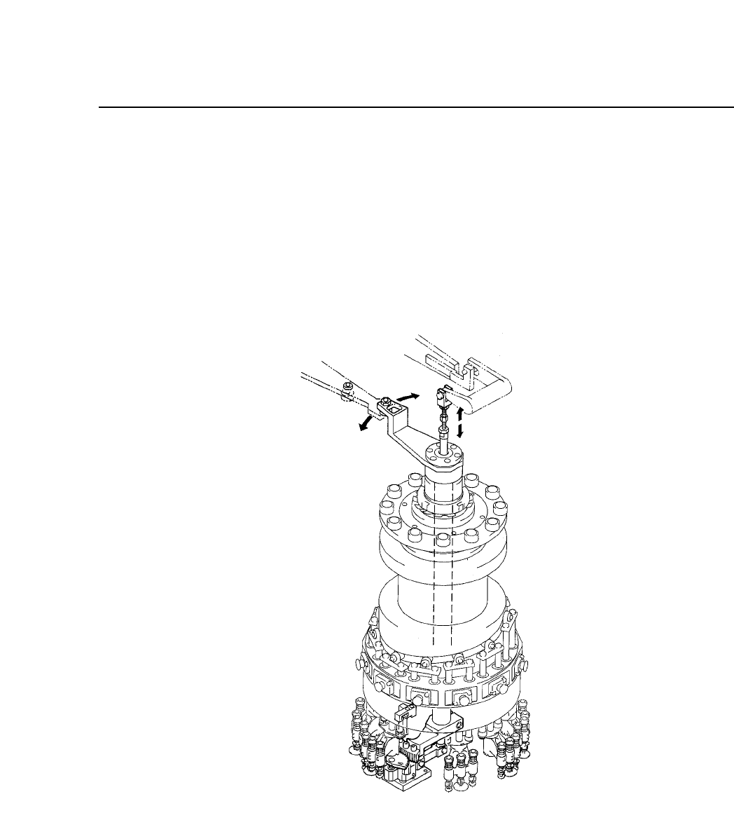
The nozzle switch operation is driven by a cam mechanism. The cam
drives a lever, which drives a shaft, which drives a lever, which drives the
holder. This sequence of drive transmission combines with the action of
the cylinder.
Fig. 5-46 Nozzle Switch Mechanism at Station 11
Adjustment requires a special jig.
CP IV-3 Maintenance
Chapter 5 The Twelve Stations
5.12 Station 12
5.12.1Nozzle Switch Check
The nozzle switch check checks whether or not the nozzle has been
correctly switched. If the nozzle has not been correctly switched,
the machine is stopped immediately to prevent damage at the next
stage.
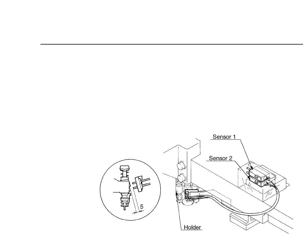
Fig. 5-47 Nozzle Switch Check Mechanism at Station 12
Follow the procedure below to adjust the nozzle switch check
mechanism.
(1) Set the cam angle to 0° and select the L nozzle. The S and M
nozzles cannot be adjusted. If the L nozzle is not selected,
remove the station 8 holder, select the L nozzle, then re-attach
the holder and rotate the unit forward to station 12. At this
time items "Y02A NOZ SOL ON" should be "O" and "Y02B
NOZ SOL OFF" should be "X". Insert a stopper so the nozzle
cannot change.
(2) Set the cam angle to 330° and adjust the sensor attachment
bracket so that the distance between the nozzle change sensor
tip and the holder is 5 mm as seen from the side (see figure 5-
49).
(3) Line up the center (looking from above) of the nozzle change
sensor and the holder (see figure 5-49).
5 – 44
Version 6.0
CP IV-3 Maintenance
5 – 45
Version 6.0
Chapter 5 The Twelve Stations
(4) Adjust the amplifier volume. Set the "on" position of sensors 1
and 2 to the point where the led changes from red to green (see
table 5-2 below).
Table 5-2 Amplifier Settings for Nozzle Switch Check
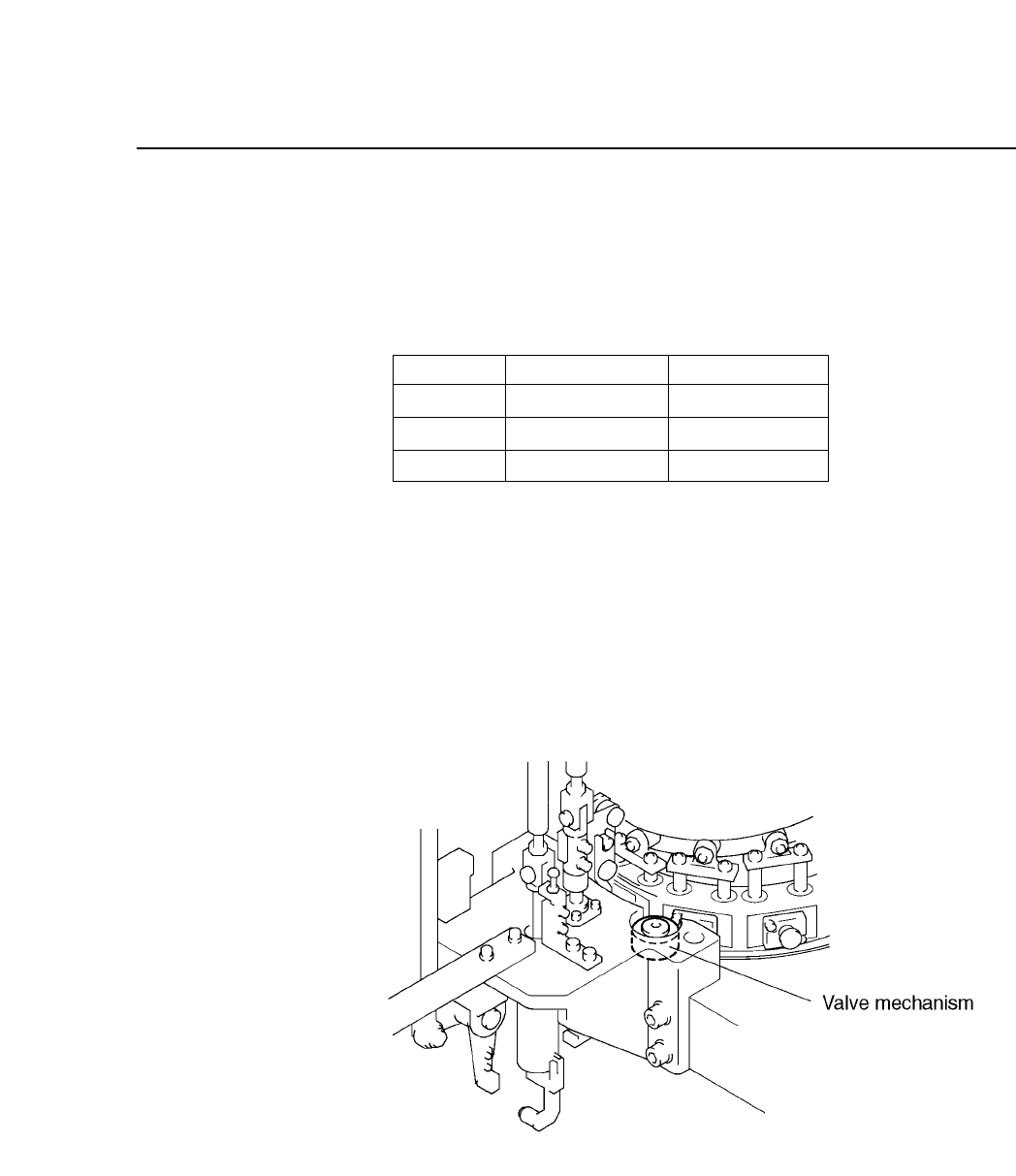
5.12.2Valve Return Mechanism
When the twelve heads are rotated backward manually (with the
handle), a valve mechanism at station 12 forces the spool to return.
Adjustment is not necessary.
Fig. 5-48 Spool Returning Mechanism at Station 12
S
L
M
Green unlit
Green lit
Green lit
Green lit
Green lit
Green unlit
Nozzle Sensor 1
Sensor 2
CP IV-3 Maintenance