CP43维护手册.pdf.pdf - 第83页
5 – 41 V ersion 6.0 Chapter 5 The T welve Stations 5.10.2 Nozzle Pre-switch Check Before nozzle change is carried out at station 1 1, the nozzle position is checked. This check, called the nozzle pre-switch check, uses t…
Chapter 5 The Twelve Stations
5.10Station 10
At station 10, parts determined to be rejects during vision processing are
thrown away. In addition, the nozzle pre-changeover check is carried out
in anticipation of the nozzle switch at station 11.
5.10.1Throwing Away Reject Parts
At Station 10, if the part was determined to be NG (no good) as a
result of vision processing at Station 4, then the rejects parts
disposal mechanism pushes down the spool cutting the air supply
to the vacuum, so the part releases from the nozzle and falls into
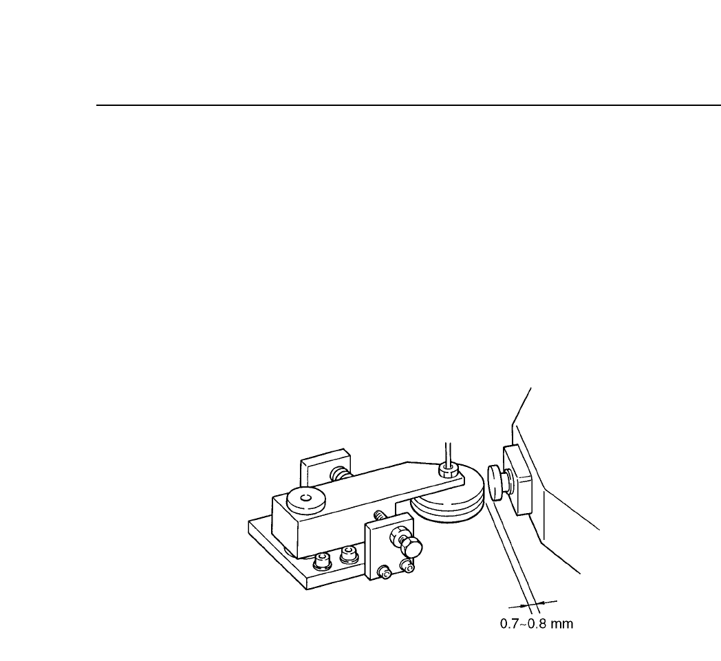
Fig. 5-44 Reject Parts Disposal Mechanism
Follow the procedure below to adjust the activation operation of
the reject parts disposal mechanism.
(1) With the cam angle set to 330° and the spool pushed in, adjust
the set bolts on the side of the roller so that there is 0.7 to 0.8
mm between the roller and the spool.
(2) Turn the roller so that the hole from which the air is expelled
matches the hole on the spool from which the air is drawn in.
(3) After the adjustment, check that the pooled out spool returns to
the pulled out position, manually using the roller. For the air
release valve, tighten the knob completely, and then loosen 3.0
rotations.
5 – 40
Version 6.0
CP IV-3 Maintenance
5 – 41
Version 6.0
Chapter 5 The Twelve Stations
5.10.2Nozzle Pre-switch Check
Before nozzle change is carried out at station 11, the nozzle position
is checked. This check, called the nozzle pre-switch check, uses two
sensors to detect the position of the S, M, L nozzles. Because this
check is performed, no problems arise if the nozzle position is
changed by the operator at a station before station 10.
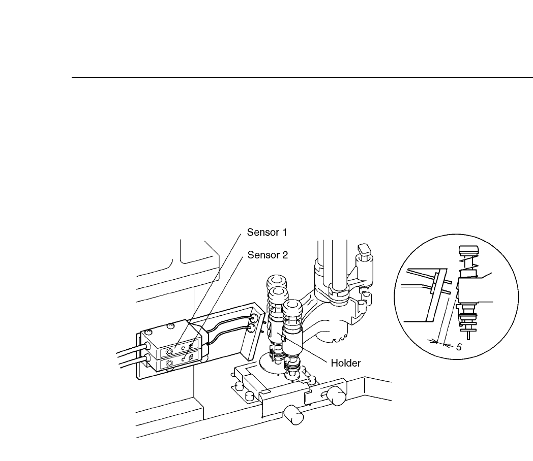
Fig. 5-45 Nozzle Pre-switch Check Mechanism
Follow the procedure below to adjust the nozzle pre-switch check
sensors.
(1) Set the cam angle to 0° and select the L nozzle. The S and M
nozzles cannot be adjusted. If the L nozzle is not selected,
remove the Station 8 holder, select the L nozzle, then re-attach
the holder and rotate the unit forward to station 10.
(2) Set the cam angle to 235° and adjust the sensor attachment
bracket so that the distance between the nozzle change sensor
tip and the holder is 5 mm as seen from the side ( see figure 5-
47).
(3) Line up the center (looking from above) of the nozzle change
sensor and the holder (see figure 5-47).
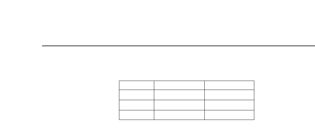
(4) Adjust the amplifier volume. Set the "on" position of sensors 1
and 2 to the point where the LED changes from red to green,
and then set the volume to the next higher mark on the dial.
CP IV-3 Maintenance
Chapter 5 The Twelve Stations
Table 5-1 Amp Settings for Nozzle Pre-switch Check
S
L
M
Green unlit
Green lit
Green lit
Green lit
Green lit
Green unlit
Nozzle Sensor 1
Sensor 2
5 – 42
Version 6.0
CP IV-3 Maintenance