CP43维护手册.pdf.pdf - 第64页
Chapter 5 The T welve Stations 5.3 Station 3 At station 3, the part is rotated to the initial theta axis position. This function is termed “pre-r otation” and abbr eviated to P θ . The pr e-r otation function rotates the…
5 – 21
Version 6.0
Chapter 5 The Twelve Stations
5.2 Station 2
At Station 2, sensors check for the presence of large parts.
Misalignment of the tape with the pickup point is one cause of pickup
errors when working with large parts. If a sensor determines a part to be
missing, it may in fact be misaligned with the pickup point and thus
vulnerable to being hit by the waste tape cutter. Therefore, if a part is
judged to be missing, the machine stops to prevent the loss that might be
incurred by having a large, expensive part damaged by the waste tape
cutter.
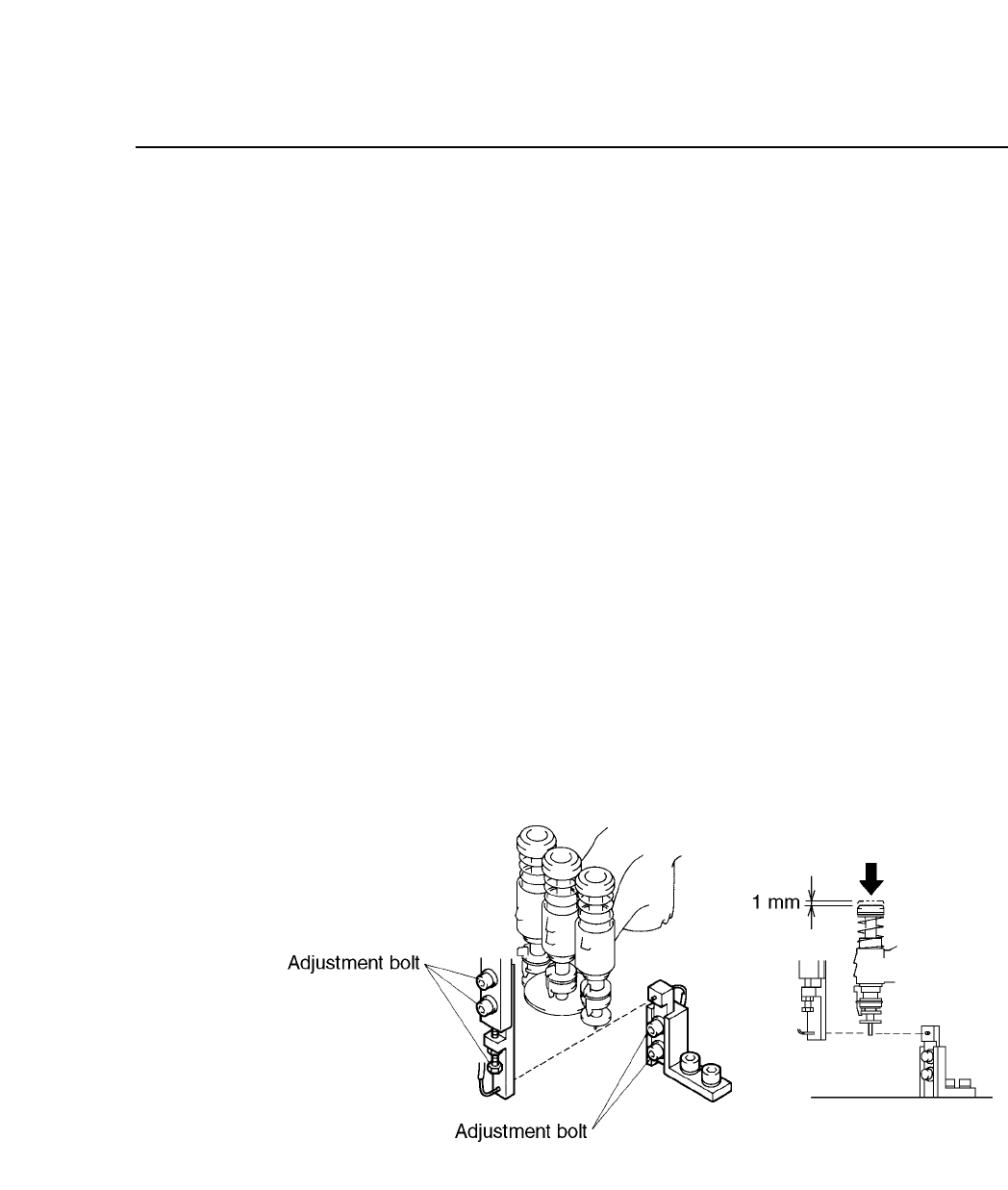
Follow the procedure below to adjust the station 2 sensors.
(1) Engage only the 100V power supply.
(2) Attach the cam handle on the handle shaft. Turn the handle until the
cam angle indicator reads 230°.
(3) With the cam angle at 230°, lower the L nozzle 1 mm (measure with a
ruler as shown in the illustration below). Adjust so that the tip of the
L nozzle will trigger the sensor.
Fig. 5-22 Large Parts Presence Check Sensor
CP IV-3 Maintenance
Chapter 5 The Twelve Stations
5.3 Station 3
At station 3, the part is rotated to the initial theta axis position. This
function is termed “pre-rotation” and abbreviated to Pθ. The pre-rotation
function rotates the part picked up at station 1 to approximately the angle
specified in the program. Pre-rotation reduces the cycle time by reducing
the time spent to perform fine rotational adjustment (Fθ) at station 6 after
vision processing has been performed at station 4.
However, pre-rotation can only be carried out in units of 90°; parts are
rotated +90°, 0°, or –90°. If a program calls for a part to be rotated 180°,
the part is first rotated either +90° or –90° at station 3. Then at station 6,
the part is rotated the remaining 90° plus the number of degrees necessary
for fine rotational adjustment. Thus parts that require 180° rotation
slightly lengthen cycle time.
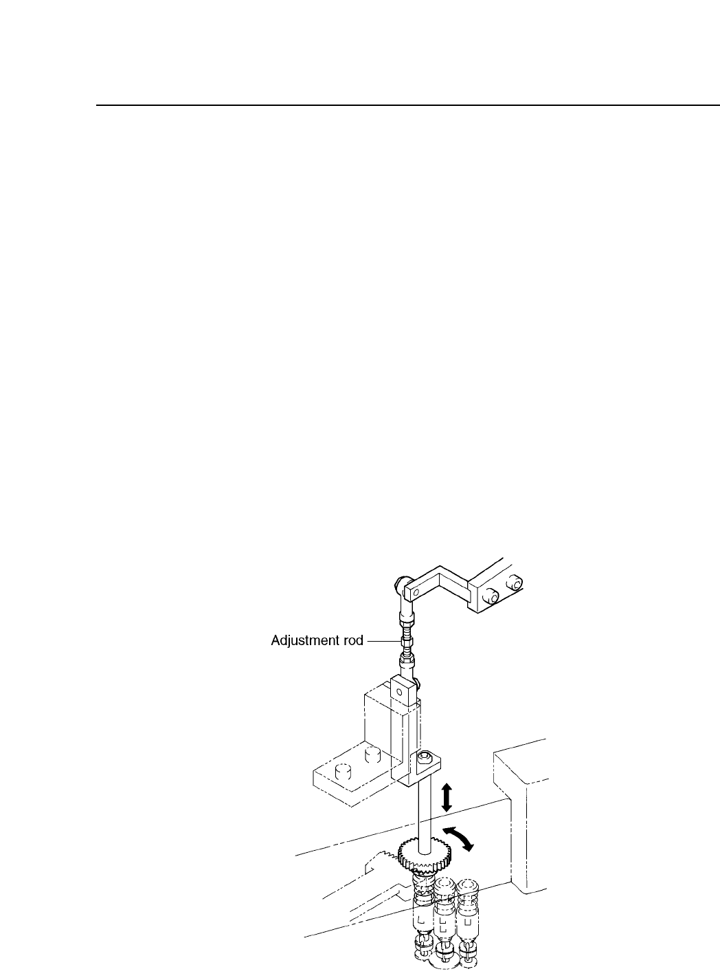
Pre-rotation involves vertical movement as well as rotation in the θ
direction.
Pre-rotation is driven by cam and cylinder mechanisms. The cam drives a
lever, which drives a rod, which drives a lever, which drives the clutch,
which rotates the cylinder +90° or –90°.
Fig. 5-23 Pre-rotation (P
θ
) Mechanism at Station 3
5 – 22
Version 6.0
CP IV-3 Maintenance
5 – 23
Version 6.0
Chapter 5 The Twelve Stations
The rotational angle of the clutch is determined by the curve of the cam;
thus, it need not be adjusted. However, the vertical setting of the clutch
and the backlash of the gear must be adjusted. These adjustments should
be performed with the power off.
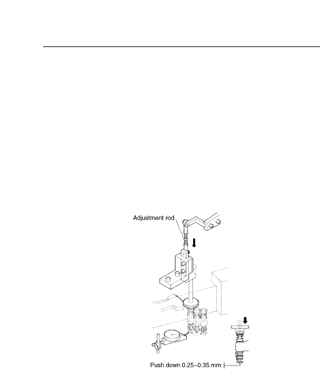
Clutch Vertical Adjustment
(1) Press [SET], [MANUAL], [I/O] and [OUT] to access the IO map. Turn
"YO22 PQ ROT SOL ON" to ON and "YO23 PQ ROT SOL OFF" to OFF
and remove the stopper so the lever can move freely.
(2) With the cam at 0° touch the dial gauge to the fluorescent disk and set
the gauge to zero.
(3) Using the cam handle, turn the cam handle backwards to 260°.
(4) With the cam angle at 260°, adjust the adjustment rod so the nozzle
pushes the dial gauge down to 0.25 to 0.35 mm.
Fig. 5-24 Pre-theta (Station 3) with Cam at 260°
CP IV-3 Maintenance