CP43维护手册.pdf.pdf - 第74页
Chapter 5 The T welve Stations (6) After completing adjustment, unscrew the four bolts holding the motor securing bracket. Remove the motor gear starting with the top part of the backlash gear . The motor and bracket are…
5 – 31
Version 6.0
Chapter 5 The Twelve Stations
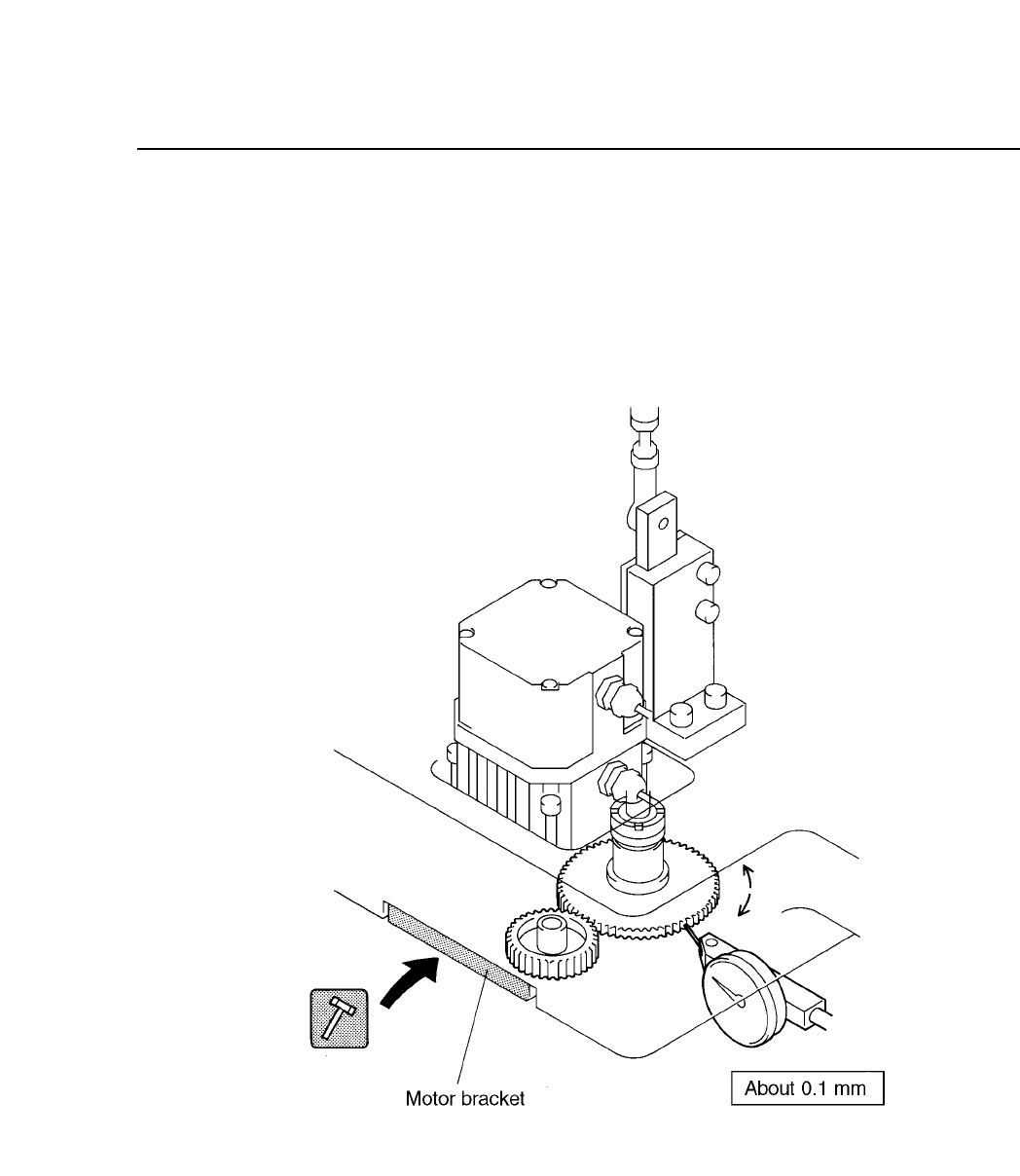
(4) Place the dial gauge on the top half of the backlash gear.
(5) Rotate the top half of the backlash gear by hand as shown below.
Place the dial gauge on the gear teeth as shown below. Tap the motor
securing bracket with a rubber hammer in the direction indicated by
the arrow until the amount of gear backlash is 0.1 mm. Be careful not
to hit the motor.
Fig. 5-32 F
θ
Third Backlash Adjustment
CP IV-3 Maintenance
Chapter 5 The Twelve Stations
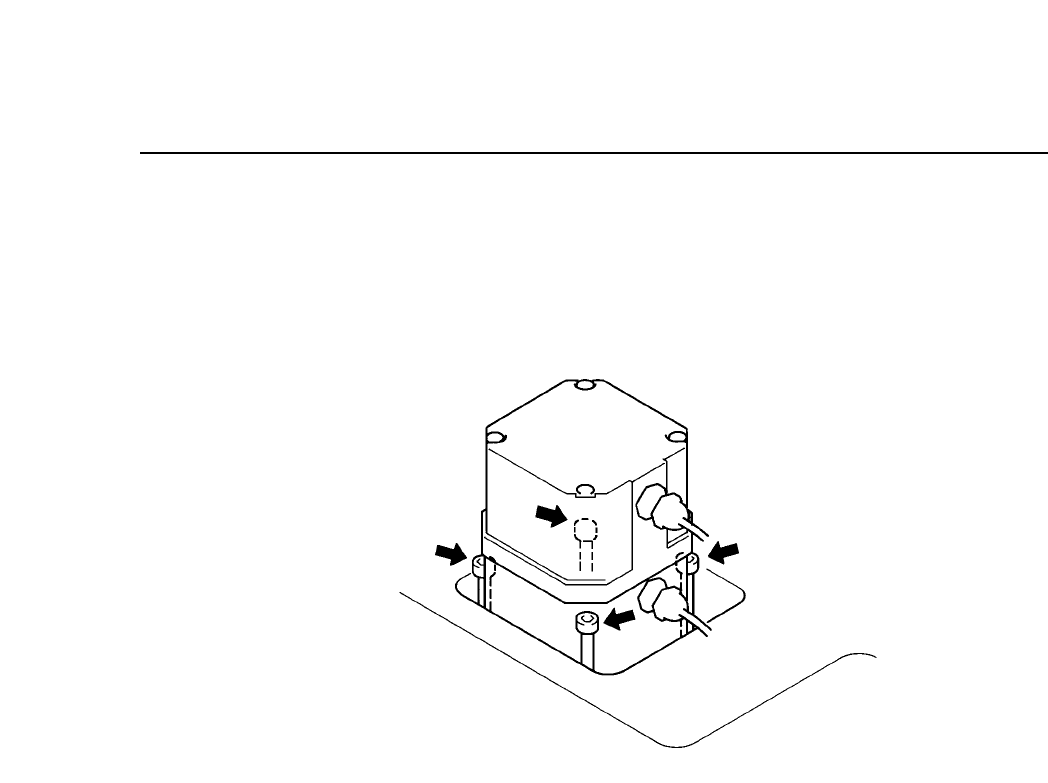
(6) After completing adjustment, unscrew the four bolts holding the
motor securing bracket. Remove the motor gear starting with the top
part of the backlash gear. The motor and bracket are interlocking
units that can be pulled apart and put back together.
Fig. 5-33 F
θ
Fourth Backlash Adjustment
(7) Attach the bottom part of the backlash gear.
(8) Reattach the motor. With the spring compressed, screw the backlash
gear on.
5 – 32
Version 6.0
CP IV-3 Maintenance
5 – 33
Version 6.0
Chapter 5 The Twelve Stations
5.7 Station 7
At station 7, in order to carry out part placement, the nozzle moves up
and down and the valve turns on and off.
5.7.1 Nozzle Up/down Stroke
The nozzle places the part on the board.
The nozzle upward and downward operation is driven by a cam
mechanism. The cam drives a lever, which drives a rod, which
drives a lever, which drives the nozzle.
The stroke of the rod is a fixed value determined by the curve of the
cam.
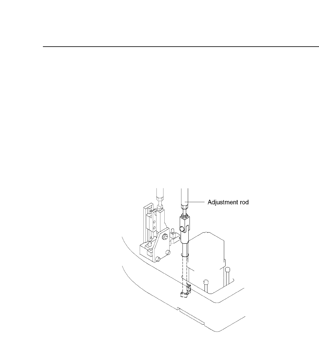
Fig. 5-34 Nozzle Vertical Operation Mechanism at Station 7
Follow the procedure below to adjust the nozzle upward and
downward stroke.
(1) Press [SET], [MANUAL], [I/O] and [EMERGENCY STOP] to
cut the 200V power but leaving the 100V power supply on.
CP IV-3 Maintenance