00193893-04.pdf - 第102页
2 Retrofit instructions - SIPLACE HF series head re confi guration kits SIPLACE HF Series Head Reconfiguration Kits 05/2006 Edition 102 : Attach the plug to the exhaust air damper . 2 : Connect the top and bottom hoses. …
SIPLACE HF Series Head Reconfiguration Kits 2 Retrofit instructions - SIPLACE HF series head reconfiguration kits
05/2006 Edition
101
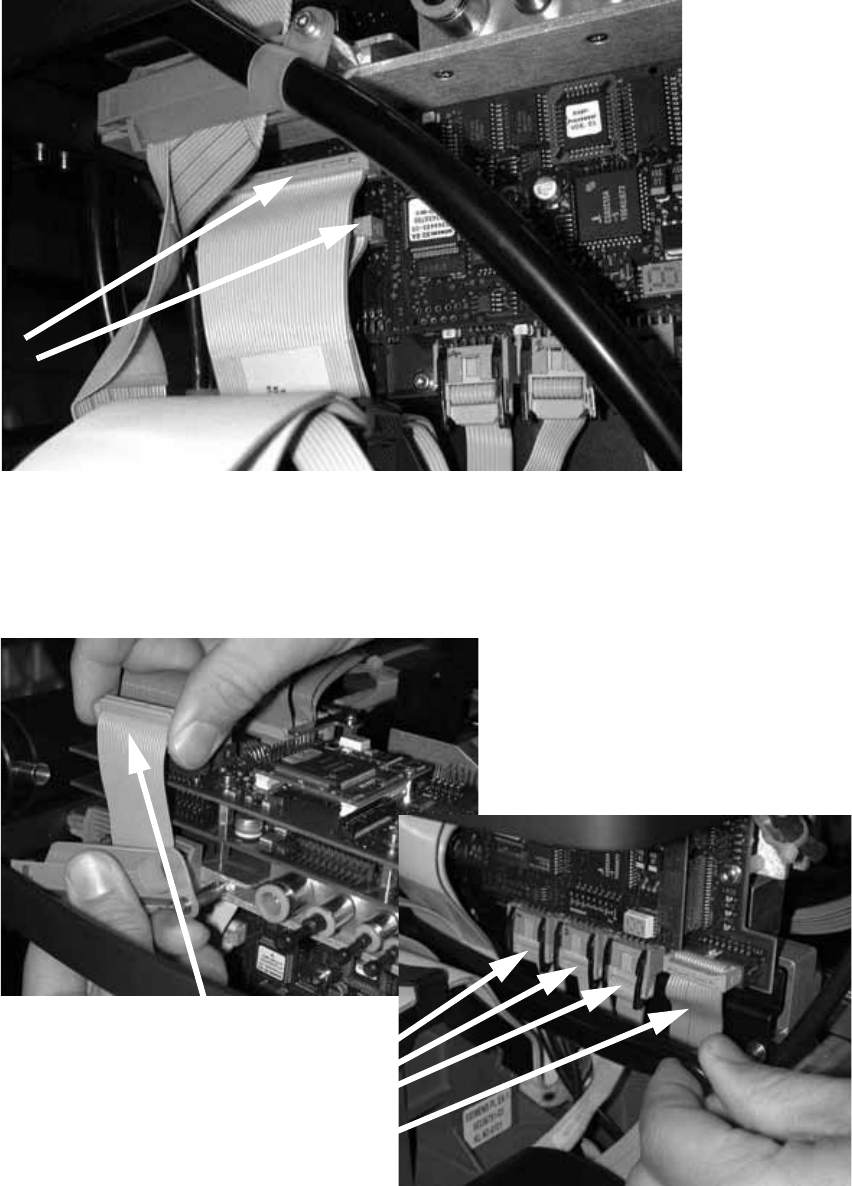
: Plug in the two connectors.
2
2
: Clip on the strain relief pushbutton.
: Attach the camera cable and the four other cables in the photograph below.
2
2 Retrofit instructions - SIPLACE HF series head reconfiguration kits SIPLACE HF Series Head Reconfiguration Kits
05/2006 Edition
102
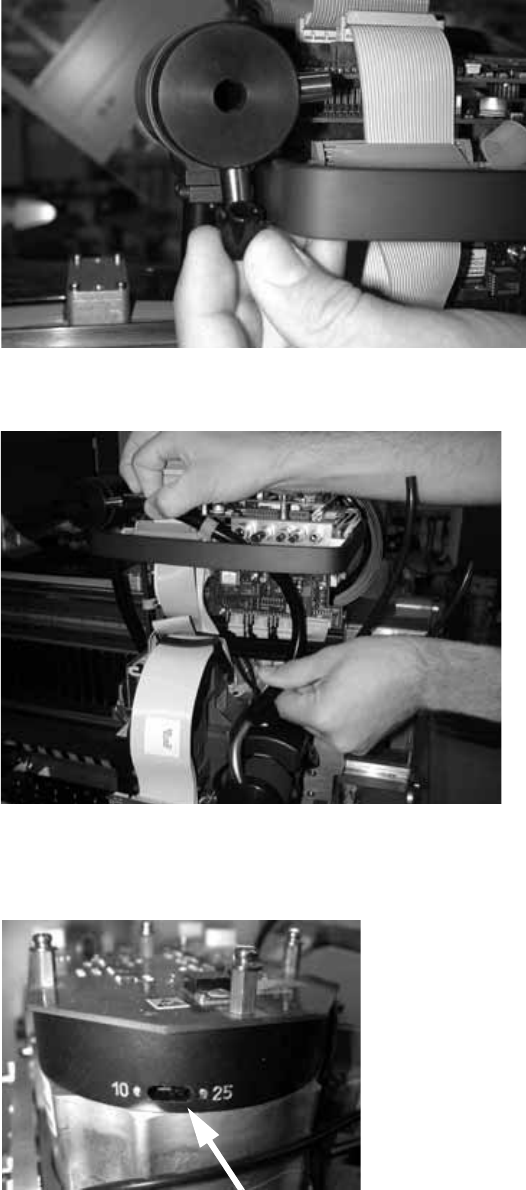
: Attach the plug to the exhaust air damper.
2
: Connect the top and bottom hoses.
2
: Set the star resolution switch to 25.
The switch can be found underneath the placement head.
2
SIPLACE HF Series Head Reconfiguration Kits 2 Retrofit instructions - SIPLACE HF series head reconfiguration kits
05/2006 Edition
103
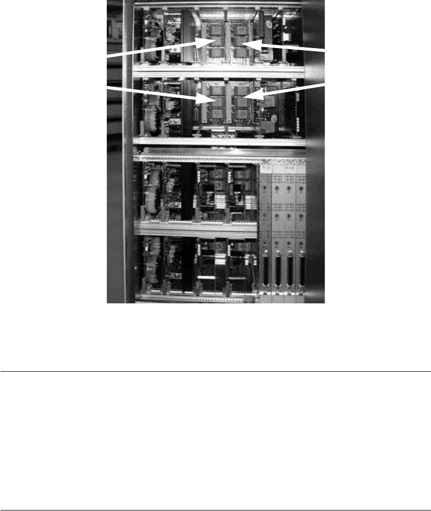
2.5.5 Replacing the servo cards
: Use the machine key to open the door of the servo unit.
: Pull out servo boards A 9, A 11, A13, and A 15 (see reference plan on the back of the door).
It is a good idea to label the servo boards to avoid any confusion.
2
2
: Insert the other appropriate servo boards into the unit.
PLEASE NOTE: 2
From software version 505 onwards, the C&P head can also be fitted on gantry 2, in which case
the servo boards must be arranged as follows if the head is converted back to the C&P head: 2
2
2
A10 A12
A14 A16
A 9
A 11
A 15
A 13