00193893-04.pdf - 第76页
2 Retrofit instructions - SIPLACE HF series head re confi guration kits SIPLACE HF Series Head Reconfiguration Kits 05/2006 Edition 76 : Place the T winHead template on the head fixing plate. Remove any excess screws and…
SIPLACE HF Series Head Reconfiguration Kits 2 Retrofit instructions - SIPLACE HF series head reconfiguration kits
05/2006 Edition
75
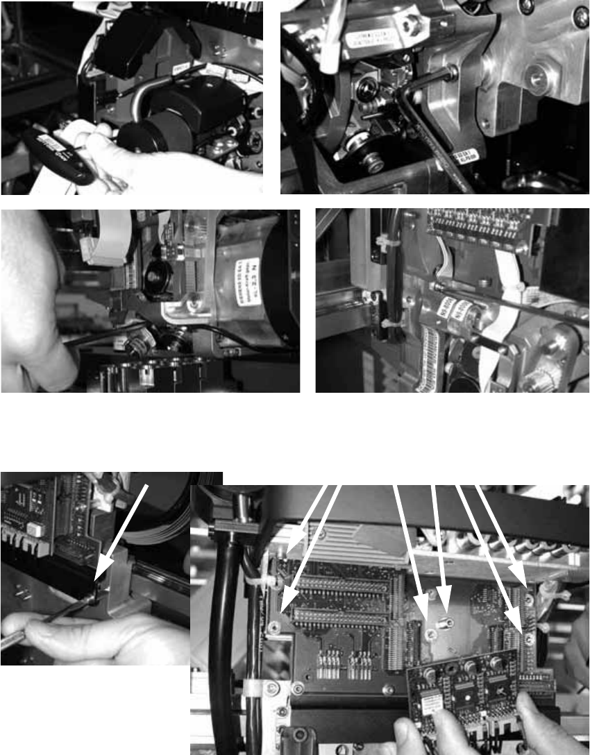
: Loosen the four screws used to fix the placement head.
With screws two and three, you should first remove one sleeve to make the screws more ac-
cessible.
2
: Loosen the screws on the rail below the head adapter board and the screws of the head ad-
apter board, and then remove both the large and the small board.
2
2
2 Retrofit instructions - SIPLACE HF series head reconfiguration kits SIPLACE HF Series Head Reconfiguration Kits
05/2006 Edition
76
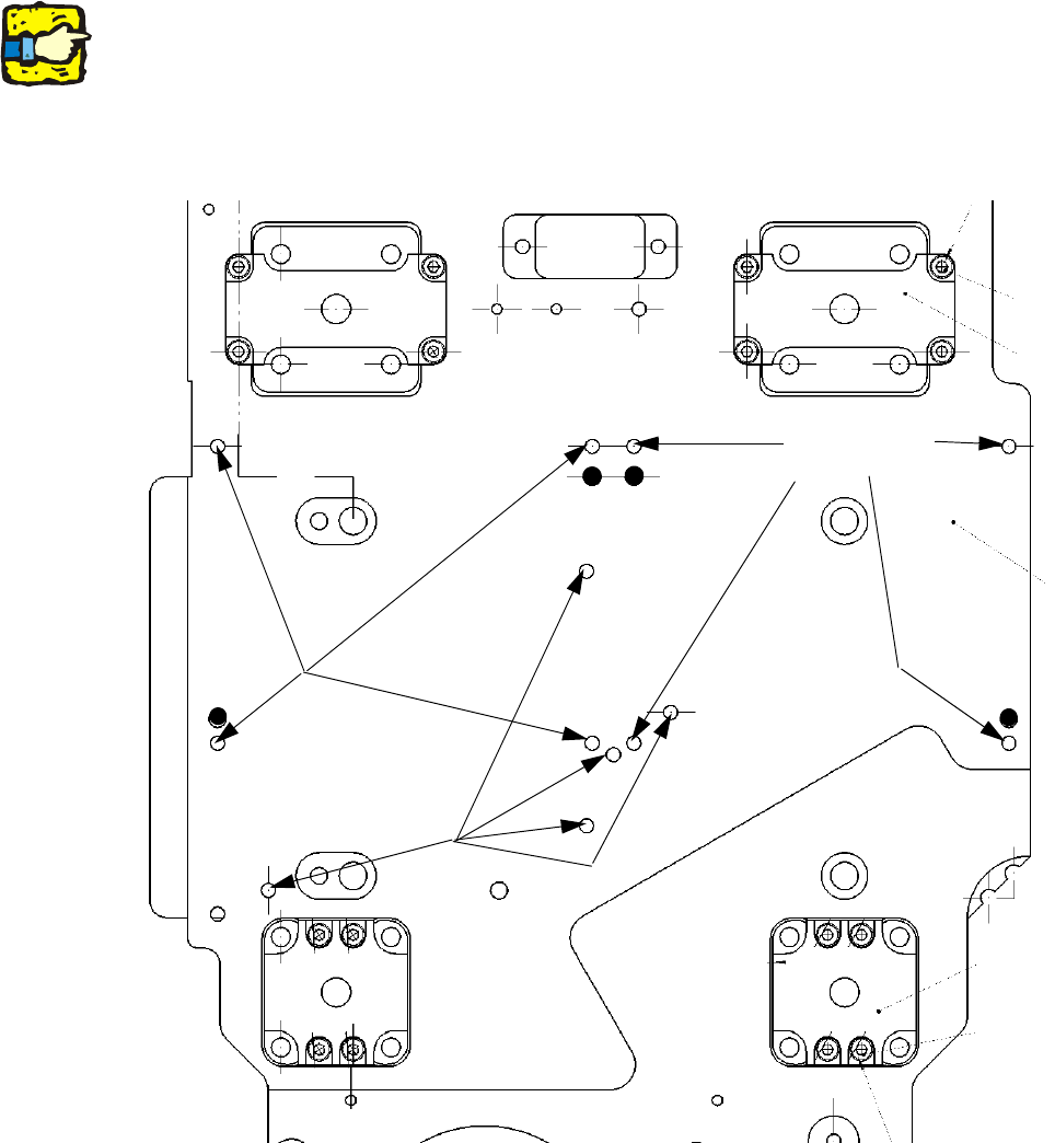
: Place the TwinHead template on the head fixing plate.
Remove any excess screws and add any necessary screws:
Fixing screws: 8x DIN 912 - M4 x 14-8.8, item no.: 00095021-01xx,
Sealing screws: 5x DIN 913 - M4 x 6-ST, item no.: 00309422-01-xx.
Screws in the wrong place could affect the flow of cooling air to the X-axis motor.
2
2
2
Always use the standard tool.
Make sure that the screws are of the right length. The lengths are different for C&P heads and the
TwinHead.
If you use the wrong screws, there is a risk of damaging the thread on the head plate.
Tightening torque for the fixing screws: 2.7 Nm. 2
2
2
Seal for
head plate
Fixing
for module 2
Fixing
for module 1
SIPLACE HF Series Head Reconfiguration Kits 2 Retrofit instructions - SIPLACE HF series head reconfiguration kits
05/2006 Edition
77
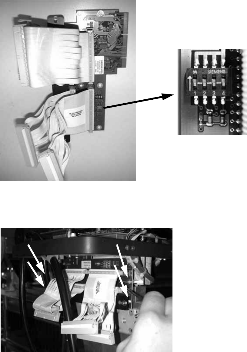
: Set all switches to OFF before installing the board.
2
2
: Plug the head adapter board from below into the head interface board (03000902-xx) and
screw in place with the four screws.
2
2