00193893-04.pdf - 第68页
2 Retrofit instructions - SIPLACE HF series head re confi guration kits SIPLACE HF Series Head Reconfiguration Kits 05/2006 Edition 68 Inserting the came ras 2 : Fix the partitio n plate for fiducials (item no.: 03022077…
SIPLACE HF Series Head Reconfiguration Kits 2 Retrofit instructions - SIPLACE HF series head reconfiguration kits
05/2006 Edition
67
2
2 Retrofit instructions - SIPLACE HF series head reconfiguration kits SIPLACE HF Series Head Reconfiguration Kits
05/2006 Edition
68
Inserting the cameras 2
: Fix the partition plate for fiducials (item no.: 03022077-xx) using two setscrews DIN 913 - M 6
x 50-ST (item no.: 03005958-)
2
The fiducial plate is very heavy. 2
2
: Fix the base plate for the IC camera onto the partition plate using two screws DIN912-M6 x
35-8.8 (item no.: 00845062-) an.
: Replace the setscrews DIN 913 - M 6 x 50-ST with the screws DIN912-M6 x 35-8.8 (item no.:
00845062-xx).
2
: Fix the base plate for the IC camera onto the partition plate using four screws (screws for fixing
the camera: DIN912-M6 x 35-8.8, item no.: 00845062-xx).
Use the top screw holes.
2
2
2
2
2
2
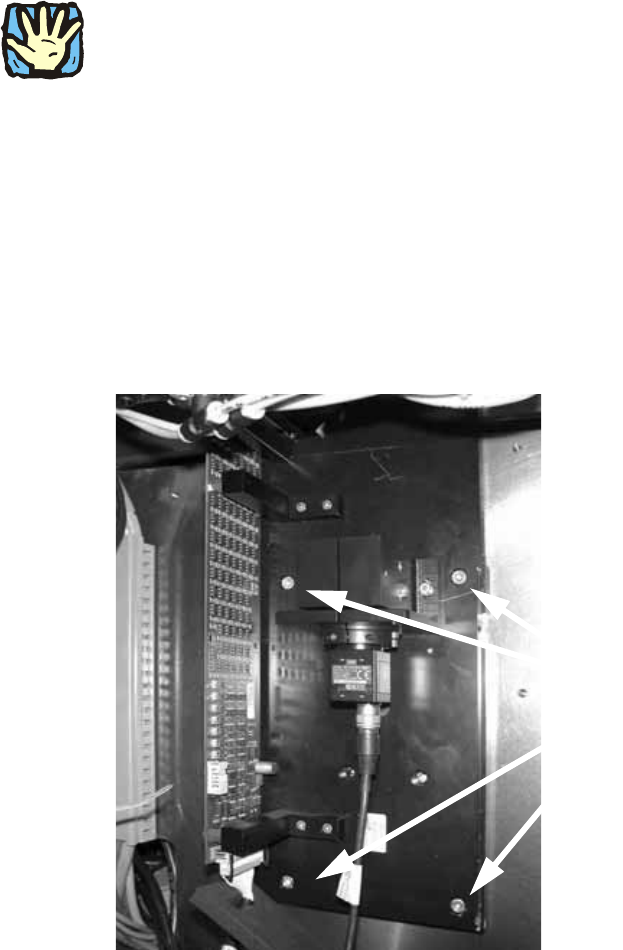
4 screws
SIPLACE HF Series Head Reconfiguration Kits 2 Retrofit instructions - SIPLACE HF series head reconfiguration kits
05/2006 Edition
69
: Place the supporting frame of the IC camera on the base plate. It should latch into place un-
derneath.
2
2
: Use the machine spirit level to check that the camera is aligned horizontally.
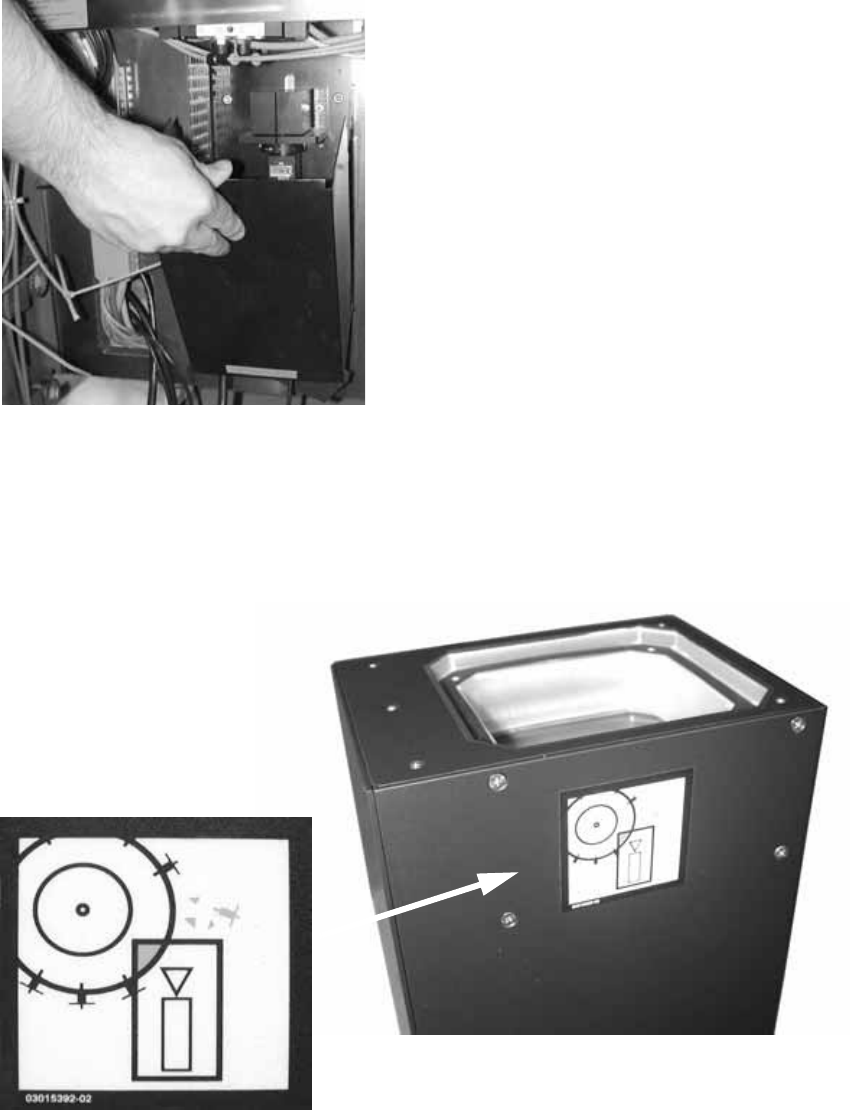
: Attach the Risk of head crash warning label to the body of the IC camera (if it is not already
attached).
2
: Then carefully place the body of the camera on the supporting frame.