00193893-04.pdf - 第99页
SIPLACE HF Series Head Reconfiguration Kits 2 Retrofit in structions - SIPLACE HF seri es head reconfiguration kits 05/2006 Edition 99 16 bit varian t 2 DO NOT inser t the 8 bit processor o n the head adapter (see previo…
2 Retrofit instructions - SIPLACE HF series head reconfiguration kits SIPLACE HF Series Head Reconfiguration Kits
05/2006 Edition
98
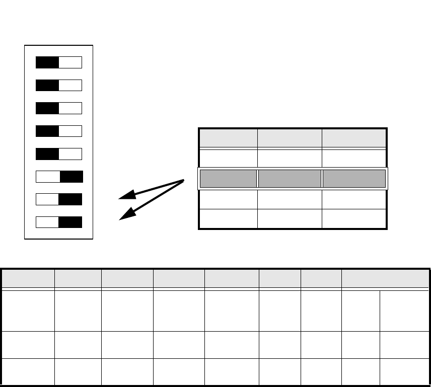
: Set the DIP switch on the processor board according to the information below.
2
Abb. 2.5.1 Table: DIP switch
2
2
2
2
2
2
2
Standard OFF OFF OFF OFF ON ON CAN_address
Switch-
setting
1
CAN_R120
2
EPROM_WE
3
Test_Mode
4
CAN_ERR_
SWITCH
5
Jumper 5
6
Jumper 6
7
CAN_ID1
8
CAN_ID0
ON X
See
above
See above
OFF X X X X X
See
above
See above
DIP Schalter
ON
78123456
Gantries Switch 7 Switch 8
Gantry 1 ON ON
Gantry 2 ON OFF
Gantry 3 OFF ON
Gantry 4 OFF OFF
SIPLACE HF Series Head Reconfiguration Kits 2 Retrofit instructions - SIPLACE HF series head reconfiguration kits
05/2006 Edition
99
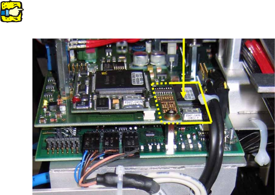
16 bit variant 2
DO NOT insert the 8 bit processor on the head adapter (see previous item) if the head interface
board is equipped with a piggyback processor TQM 167 (see photograph below). 2
The processor on the head interface then controls the placement head. 2
2
2
2
Do not confuse the vision interface with the head interface. 2
The vision interface is seated above the head interface and always has a piggyback processor
TQM 167. 2
2
2
2
2
2
2
2
2
2
2
2
2 Retrofit instructions - SIPLACE HF series head reconfiguration kits SIPLACE HF Series Head Reconfiguration Kits
05/2006 Edition
100
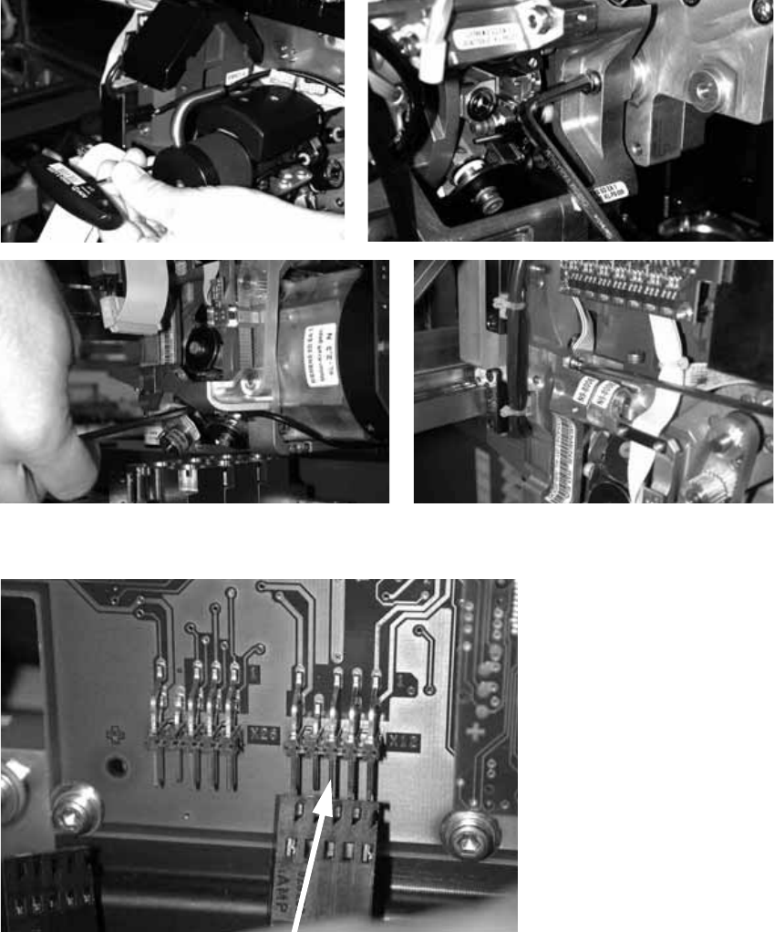
: Fit the placement head and fix in place with four screws.
Make sure that the screws are of the right length.
With screws two and three, you should first remove one sleeve to make the screws more ac-
cessible.
2
: Plug in the connectors for the DP axis.
2
2
2