Specification SIPLACE X-Series规格说明书2.pdf - 第11页
11 Machine Performance CPP_H = MultiStar CPP in high mounting position CPP_L = MultiStar CPP in low mounting positio n SIPLACE X3 placement system For the definition of the pl acement performan ce values see the note on …

10
Machine Performance
CPP_H = MultiStar CPP in high mounting position
CPP_L = MultiStar CPP in low mounting position
Types of placement head SIPLACE SpeedStar (C&P20)
SIPLACE MultiStar (CPP)
SIPLACE TwinStar (TH)
PLEASE NOTE The placement rate is affected by the different head combinations and
positions and by the conveyor configurations. Individual options and cus-
tomer-specific applications also affect the placement rate. On request,
SIPLACE can calculate the true output for your product on your machine
configuration.
IPC value [comp./h]
According to the vendor-neutral conditions of the IPC 9850 standard pub-
lished by the Association of Connecting Electronics Industries.
SIPLACE benchmark value [comp./h]
The SIPLACE benchmark value is measured during the machine accep-
tance tests. It corresponds to the conditions set out in the SIPLACE scope
of service and supply.
Theoretical maximum output value [comp./h]
The theoretical maximum output value is calculated from the most favor-
able conditions for each machine type and setting, and corresponds to
the theoretical conditions normally used in the industry.
SIPLACE X4I placement machine (I-placement mode)
For the definition of the placement performance values see the note above.
Number of gantries 4
Machine Placement area 1 Placement area 2 IPC value Benchmark value Theoretical value
X4I-A C&P20 / C&P20 C&P20 / C&P20 102,000 120,000 135,500
C&P20 / C&P20 CPP_L / CPP_L 91,500 107,000 123,750
CPP_L / CPP_L CPP_L / CPP_L 81,000 94,000 112,000
SIPLACE X4 placement system
For the definition of the placement performance values see the note above.
Number of gantries 4
Machine Placement area 1 Placement area 2 IPC value Benchmark value Theoretical value
X4-A C&P20 / C&P20 C&P20 / C&P20 82,000 90,000 124,000
C&P20 / C&P20 CPP_L / CPP_L 75,000 85,000 118,000
CPP_L / CPP_L CPP_L / CPP_L 68,000 80,000 112,000
X4-B C&P20 / C&P20 CPP_H / TH 61,900 68,600 93,000
CPP_L / CPP_L CPP_H / TH 54,900 63,600 87,000
X4-C C&P20 / C&P20 TH / TH 48,000 52,500 75,000
CPP_L / CPP_L TH / TH 41,000 47,500 69,000
X4-D CPP_H / TH TH / TH 27,900 31,100 44,000
X4-E TH / TH TH / TH 14,000 15,000 26,000

11
Machine Performance
CPP_H = MultiStar CPP in high mounting position
CPP_L = MultiStar CPP in low mounting position
SIPLACE X3 placement system
For the definition of the placement performance values see the note on page 10.
Number of gantries 3
Machine Placement area 1 Placement area 2 IPC value Benchmark value Theoretical value
X3-A C&P20 / C&P20 C&P20 62,700 69,500 93,000
C&P20 / C&P20 CPP_L 59,200 66,500 90,000
CPP_L / CPP_L CPP_L 52,200 61,500 84,000
X3-B C&P20 / C&P20 TH 45,300 50,000 68,500
CPP_L / CPP_L TH 38,300 45,000 62,500
X3-C CPP_H / TH TH 25,200 28,600 37,500
X3-D TH / TH TH 11,300 12,500 19,500
SIPLACE X2 placement system
For the definition of the placement performance values see the note on page 10.
Number of gantries 2
Machine Placement area 1 Placement area 2 IPC value Benchmark value Theoretical value
X2-A C&P20 C&P20 43,400 49,000 62,000
C&P20 CPP_L 39,900 46,000 59,000
CPP_L CPP_L 36,400 43,000 56,000
X2-B C&P20 TH 26,000 29,500 37,500
CPP_L TH 22,500 26,500 34,500
X2-C TH TH 8,600 10,000 13,000
12
Placement Heads
Overview
Head modularity
The SIPLACE X series is
characterized by maximum
flexibility in the production
process. This flexibility is
partly due to the head modu-
larity of the placement
machines as it allows differ-
ent placement head variants
to be configured to suit the
production requirements.
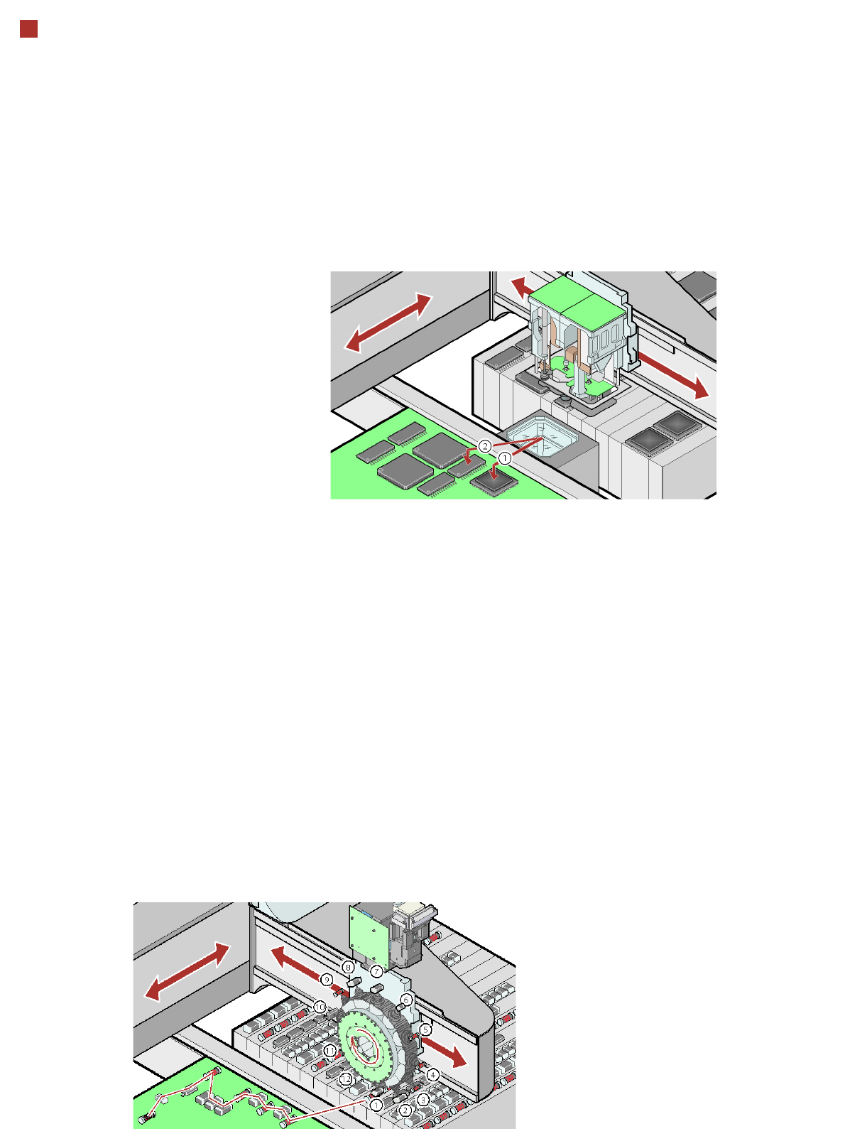
Collect&Place principle
The SIPLACE SpeedStar
works on the Collect & Place
principle. This means that,
within each cycle, 20 compo-
nents are picked up or “col-
lected”, are optically cen-
tered on the way to the board
and are rotated into the
required placement position.
They are then placed gently
and accurately on the PCB.
This principle is particularly
suitable for the high-speed
placement of standard com-
ponents.
Pick&Place principle
The high-precision SIPLACE
TwinStar, which consists of
two Pick&Place placement
modules of the same design,
works on the Pick&Place
principle. Two components
are picked up by the place-
ment head, optically cen-
tered on the way to the
placement position and
rotated into the necessary
placement angle. This princi-
ple has proved particularly
suitable for fast and accurate
placement of special compo-
nents in the fine pitch and
super-fine pitch range, and
for complex and heavy com-
ponents that require grip-
pers, for example.
Mixed Mode
The new SIPLACE MultiStar
works with both the Collect&
Place and the Pick&Place
principle. In mixed mode, it
can combine these two
modes (which were previ-
ously kept strictly separate)
in a single placement cycle.
Checking and self-learning
functions
The SIPLACE placement
heads' reliability can be fur-
ther increased with various
checking and self-learning
functions.
• Component sensors
check for the presence of
a component at the nozzle
before and after the pick-
up and placement pro-
cess.
• Digital cameras check the
position of each compo-
nent at the nozzle. Any
deviations from the
required pick-up position
are corrected before
placement takes place.
• Force sensors monitor the
specified component set-
down forces. With the sen-
sor stop method, differ-
ences in height during
pick-up and any warping
of the PCB are compen-
sated during placement.
• Vacuum sensors check
whether the component
was picked up or set down
correctly.