Specification SIPLACE X-Series规格说明书2.pdf - 第34页
34 Digital SIPLACE Vision System Checking the Component Quality Overview of the Most Important Functions Detecting collinea rity of the leads Damaged or bent leads are detected, thus avoiding unsolde red connections dur …

33
Digital SIPLACE Vision System
The digital vision system
guarantees extremely fast
and reliable component rec-
ognition, while being very
simple to use. The system
identifies each individual
component from its shape
and color. Even complex
component shapes, such as
flip-chip or CCGA are
detected extremely reliably.
The system is not only used
in the placement head cam-
eras; it can also be found in
the PCB camera. As well as
ensuring that components
are detected accurately, it
also ensures reliable detec-
tion of the ink spots and PCB
fiducials.
The benefits at a glance:
• Extremely fast and reliable
component detection
• Shortest cycle times
• Robust measurement with
reference to the shape
and color
• Straightforward program-
ming
• Offline programming of
package forms
• Rapid introduction of new
products (NPI)
• Open architecture allows
you to quickly adapt to
new requirements
• Optimum placement
results through individual
measurement of each
component
Digital vision cameras
SIPLACE SpeedStar camera, type 23
SIPLACE MultiStar camera, type 30
SIPLACE TwinStar camera, type 33 (standard)
SIPLACE TwinStar high resolution camera, type 25
SIPLACE PCB camera, type 34 (standard)
Examples of digital vision system analysis times
Analysis times are only important for the P&P process.
01005 9 ms
PLC44 17 ms
BGA 225 balls 18 ms
The SIPLACE vision system
provides testing routines and
functions that increase the
component recognition qual-
ity.
The benefits at a glance:
• Maximum placement
quality
• High first pass yield
• Reduced operating costs
34
Digital SIPLACE Vision System
Checking the Component Quality
Overview of the Most Important Functions
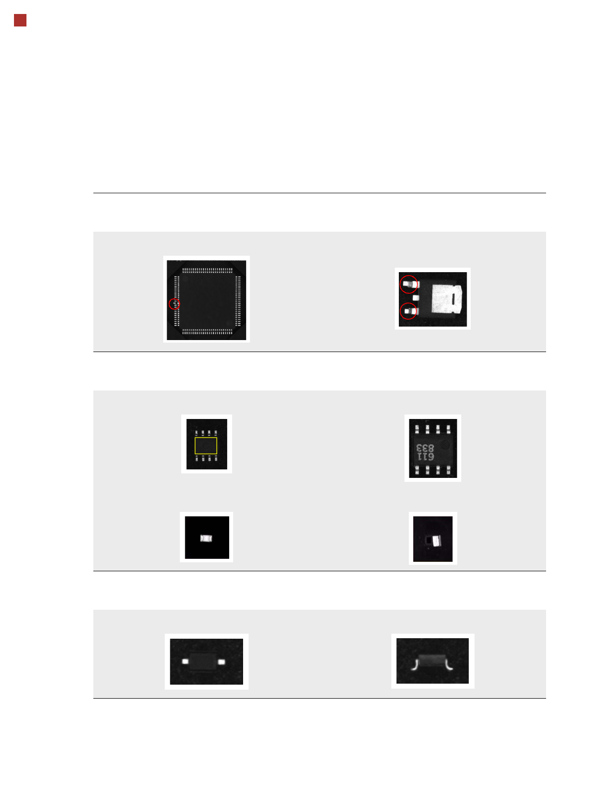
Detecting collinearity of the leads
Damaged or bent leads are detected,
thus avoiding unsoldered connections during the subsequent soldering process.
Damaged leads
Detecting flipped (face-down) or standing components
Flipped (face-down) or standing components are detected
on both chip and IC models (e.g. SOT).
SOT OK SOT face-down
Chip flipped Chip standing
Checking the lead width
The optical check of the lead width detects sloping or damaged leads.
This allows diodes with sloping leads, for example, to be detected.
Lead width OK Sloping lead
35
Digital SIPLACE Vision System
Checking the Component Quality
Overview of the Most Important Functions
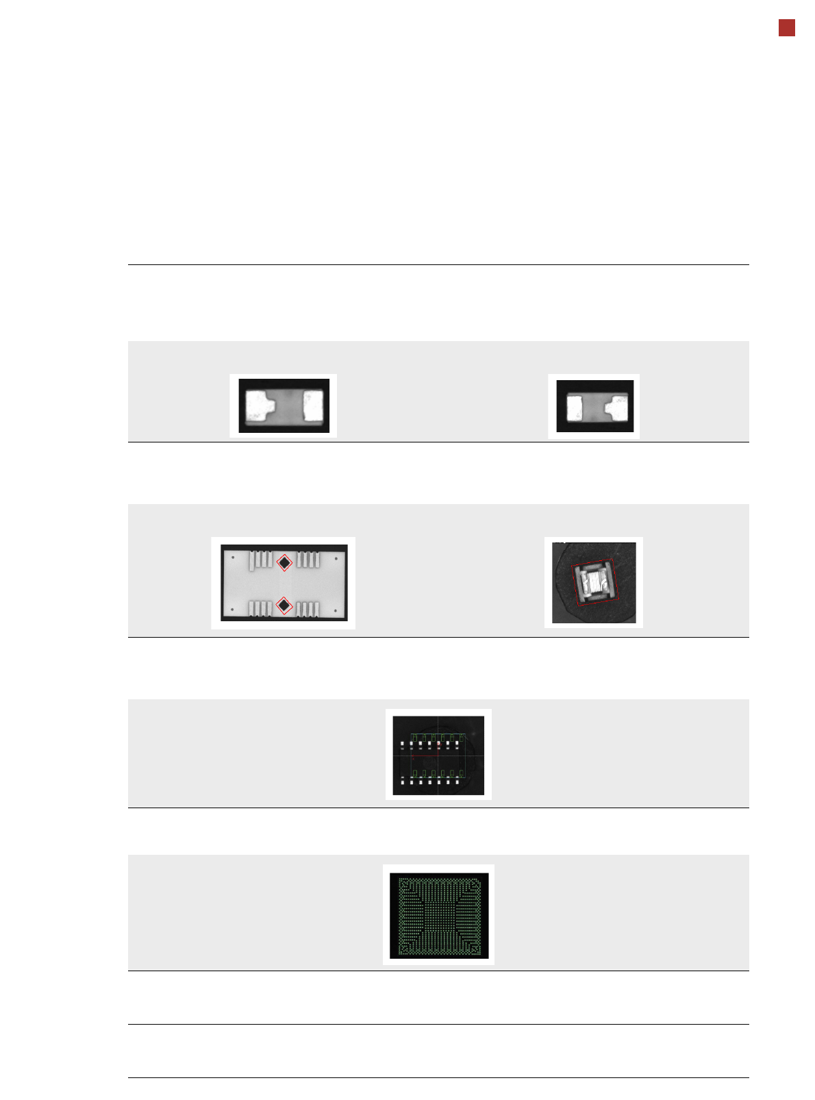
Checking the lead length
The lead length check detects whether the lead is twisted.
This can occur with chip models, for example, due to the different lengths of the two leads.
Flipped and rotated components are also detected.
Component in this position is OK Rotated
Detecting special models with rectangular functions
With certain special models, parts on the component or outer contour have to be
programmed as rectangular models so that they can be processed more reliably.
Rectangular function on the component Rectangular component with non-uniform boundaries
Detecting incorrect component descriptions
The vision system checks whether the position of the component agrees with the measured vision data. In the
following example there are actually more leads than were programmed in the package form description.
Teaching complex BGA structures
Complex BGA structure can be taught within a few seconds.
Placing when there is no ink spot
It is now possible to define a fiducial for omitting subpanels.
If a fiducial (cross, circle, etc.) is found, this subpanel will be omitted.
Checking the inner area of circular fiducials
To make circular fiducials easier to distinguish from other structures on the PCB,
a brightness check is carried out in the inner area of these fiducials.