Specification SIPLACE X-Series规格说明书2.pdf - 第52页
52 Technical Data Siemens Signal Interface Signal Sequence 1. After swit ching on t he statio n Transport direction Belt n Belt n+1 PCB sensor PCB sensor Station n transports PCB to the transfer position Belt n running B…

51
Technical Data
Siemens Signal Interface
Connector Assignment
Signal interface (20-pin ribbon cable connector)
Upstream station X1 Downstream station X2
Pin 1 Reserved Pin 1 Reserved
Pin 2 GND 24 VDC Pin 2 Reserved
Pin 3 + 24 VDC Pin 3 Reserved
Pin 4 Reserved Pin 4 Reserved
Pin 5 Reserved Pin 5 GND 24 VDC
Pin 6 Reserved Pin 6 + 24 VDC
Pin 7 Reserved Pin 7 Reserved
Pin 8 Reserved Pin 8 Reserved
Pin 9 Reserved Pin 9 Reserved
Pin 10 Reserved Pin 10 Reserved
Pin 11 Interfering signal loop Pin 11 Interfering signal loop
Pin 12 Interfering signal loop Pin 12 Interfering signal loop
Pin 13 GND 24 VDC Pin 13 GND 24 VDC for permission / arrived
(galvanic isolation)
Pin 14 Arrived Pin 14 Arrived
Pin 15 Permission Pin 15 Permission
Pin 16 Reserved Pin 16 Reserved
Pin 17 Reserved Pin 17 Reserved
Pin 18 Transferred Pin 18 Transferred
Pin 19 Request Pin 19 Request
Pin 20 GND 24 VDC for request / transferred
(galvanic isolation)
Pin 20 GND 24 VDC
52
Technical Data
Siemens Signal Interface
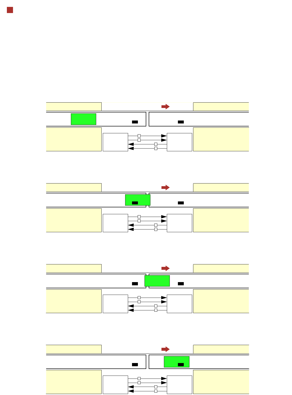
Signal Sequence
1. After switching on the station
Transport direction
Belt n Belt n+1
PCB sensor PCB sensor
Station n transports PCB
to the transfer position
Belt n running Belt n+1 stopped
Request
Transferred
Permission
Arrived
Request
Transferred
Permission
Arrived
Station n+1
is ready to receive PCBs
0
0
1
0
2. The PCB transfer has started
Transport direction
Belt n Belt n+1
PCB sensor
Station n transfers
PCB to Station n+1
Belt n running Belt n+1 running
Request
Transferred
Permission
Arrived
Request
Transferred
Permission
Arrived
Station n+1 expects
PCB from station n
1
0
1
0
3. PCB is transferred
Transport direction
Belt n Belt n+1
PCB sensor PCB sensor
Station n has
just transferred the PCB
Belt n stopped Belt n+1 running
Request
Transferred
Permission
Arrived
Request
Transferred
Permission
Arrived
Station n+1 expects PCB
from station n, but PCB
has not yet arrived.
0
1
1
0
PCB sensor
4. PCB transfer is complete
Transport direction
Belt n Belt n+1
PCB sensor PCB sensor
Station n
Belt n stopped Belt n+1 running
Request
Transferred
Permission
Arrived
Request
Transferred
Permission
Arrived
Station n+1
PCB arrived
0
0
0
1

53
Technical Data
Electrical Ratings and Compressed Air Supply
Electrical ratings
Supply voltage 3 x 200 VAC ± 5%; 50/60 Hz (Japanese version)
3 x 208 VAC ± 5%; 50/60 Hz (U.S.A. version)
3 x 230 VAC ± 5%;50/60 Hz
3 x 380 VAC ± 5%;50/60 Hz
3 x 400 VAC ± 5%; 50/60 Hz (European version)
3 x 415 VAC ± 5 %;50/60 Hz
Fuses 3 x 32 A (3 x 200 VAC / 3 x 208 VAC / 3 x 230 VAC)
3 x 16 A (3 x 380 VAC / 3 x 400 VAC / 3 x 415 VAC)
Power connector 5 x 6 mm² cable with CEKON plug 5 x 32 A (3 x 200 VAC / 208 VAC / 230 VAC)
5 x 4 mm² cable with CEKON plug 5 x 16 A (3 x 380 VAC / 400 VAC / 415 VAC)
Nominal apparent power SIPLACE X4I/X4: 4.7 kVA
SIPLACE X3: 4.1 kVA
SIPLACE X2: 3.3 kVA
Active power SIPLACE X4I/X4: 2.7 kW
SIPLACE X3: 2.15 kW
SIPLACE X2: 1.83 kW
Rated current consump-
tion
SIPLACE X4I/X4: 11.3 A / 3 x 400 VAC
SIPLACE X3: 9.7 A / 3 x 400 VAC
SIPLACE X2: 8.1 A / 3 x 400 VAC
Compressed air supply
Compressed air ratings
p
min
p
max
0.5 MPa = 5.0 bar
1.0 MPa = 10 bar
Operating pressure 0.48 MPa ± 0.025 MPa (4.8 bar ± 0.25 bar)
Compressed air connec-
tion
R 3/4“ internal thread (pipe thread) with 1/2“ hose connector
Type of machine Placement head configuration Compr. air consmpt.
a
without vacuum
pump
a) Under normal atmospheric conditions at 20°C and 1013 hPa.
-Compr. air
consmpt.
a
with vacuum pump
b
b) Vacuum pump for the C&P20 head only.
SIPLACE X4I/X4
SIPLACE X3
SIPLACE X2
C&P20/C&P20/C&P20/C&P20
C&P20/C&P20/CPP/CPP
CPP/CPP/CPP/CPP
C&P20/C&P20/C&P20
C&P20/C&P20/CPP
CPP/CPP/CPP
TH/TH/TH
C&P20 / C&P20
C&P20/CPP
CPP/CPP
TH / TH
960 Nl/min
720 Nl/min
480 Nl/min
720 Nl/min
600 Nl/min
360 Nl/min
300 Nl/min
480 Nl/min
360 Nl/min
240 Nl/min
200 Nl/min
220 Nl/min
350 Nl/min
–
165 Nl/min
230 Nl/min
–
–
110 Nl/min
175 Nl/min
–
–
Compressed air specification according to ISO 8573
Particle size 5 µm (ISO class 3)
Particle density 5 mg/m³ (ISO class 3)
Maximum oil content 0.01 mg/m³ (ISO class 1)
Pressure dewpoint + 3°C (ISO class 4)