TR7600 SIII_Series_Maintenance_en_v_2_0_3.pdf - 第33页
Test Research, Inc . TR7600 SII I Series User Guide – Maintenance 23 Figure 37: Emergency Stop 4.5 Check the Gate Move ment Use the HM I to test if the movement s of left and right gates can work w ell. Figure 38: Left a…
Test Research, Inc.
22 TR7600 SIII Series User Guide – Maintenance
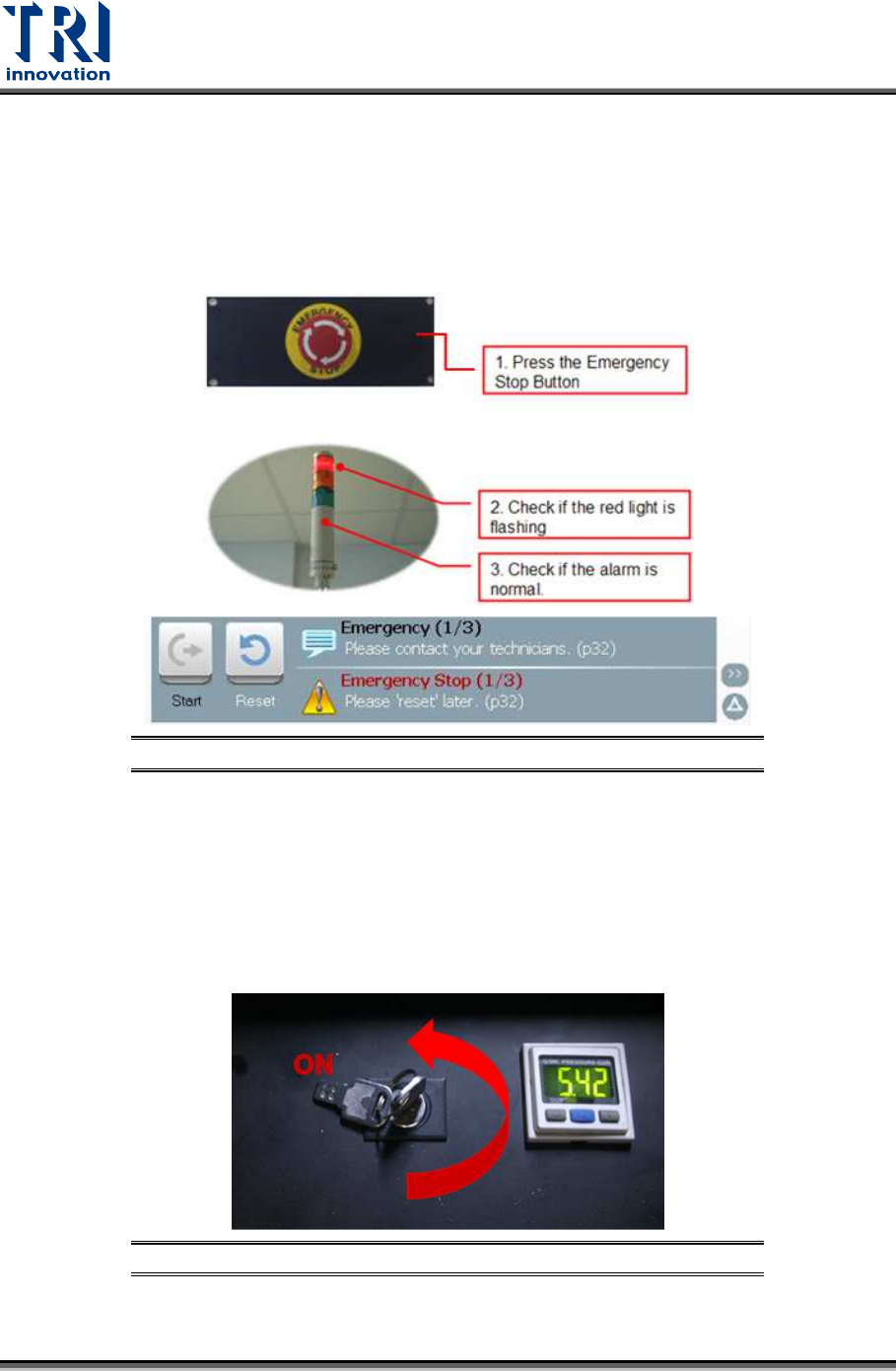
4.3 Check Emergency Stop
Press front, right, left and rear emergency stops to test if the emergency stop is working well.
If the emergency stop button is pressed, the HCI screen will display [Emergency Stop] in red.
Red light on the signal tower will be on and an alarm will sound. After the function is properly
tested, turn the emergency stop button clockwise and press [Reset] to reset it. No need to
re-start the power of the machine after the test.
Figure 35: Emergency Stop Checking
4.4 Check Interior Safety Lock
Test if the interior safety lock in the front door is working properly. Turn the interior safety
lock to “ON”, then test if the system properly performs an emergency stop (the HCI screen
will display [Emergency Stop] in red, the red light on the signal tower will come on and an
alarm will sound.) when the front door, rear door or side gates are open. After the function is
tested, turn the emergency stop button clockwise and press [Reset] to reset it. No need to
re-start the power of the machine after the test.
Figure 36: Safety Lock Position
Test Research, Inc.
TR7600 SIII Series User Guide – Maintenance 23
Figure 37: Emergency Stop
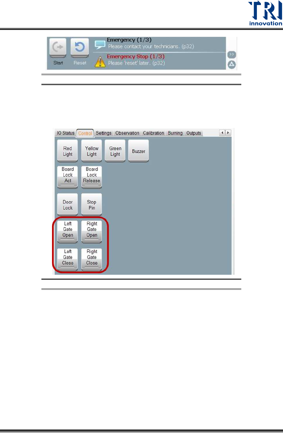
4.5 Check the Gate Movement
Use the HMI to test if the movements of left and right gates can work well.
Figure 38: Left and Right Gate Motion Checking
4.6 Check Back Fans Operating
Check the back fans if the fans are working properly.
Test Research, Inc.
24 TR7600 SIII Series User Guide – Maintenance
4.7 Clean Front Door Screen
Check if the lead glass window is clean; if not, use a soft cloth to clean it.
Figure 39: Front Window Checking and Cleaning
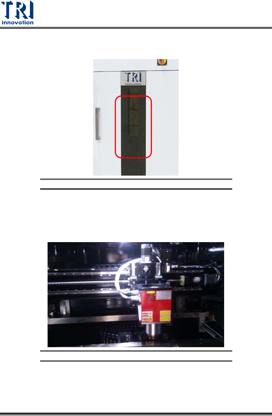
4.8 Clear Objects inside Machine
Confirm there is no foreign materials/objects or interference inside the system that will affect
inspections.
Figure 40: Inside Machine/X-ray Tube & Conveyor