00194086-01.pdf - 第141页
User Manual SIPLAC E CS 6 Component handling Software Vers ion SR.408.xx 03/2006 U S Edition 6.2 Technical da ta for the S feeder modules 141 6.2.10.2 T echnical dat a 6 6 6 6.2.10.3 Parameters for surf t ape feeder modu…
6 Component handling User Manual SIPLACE CS
6.2 Technical data for the S feeder modules Software Version SR.408.xx03/2006 US Edition
140
6.2.10 Surf tape feeder module
6.2.10.1 Overview
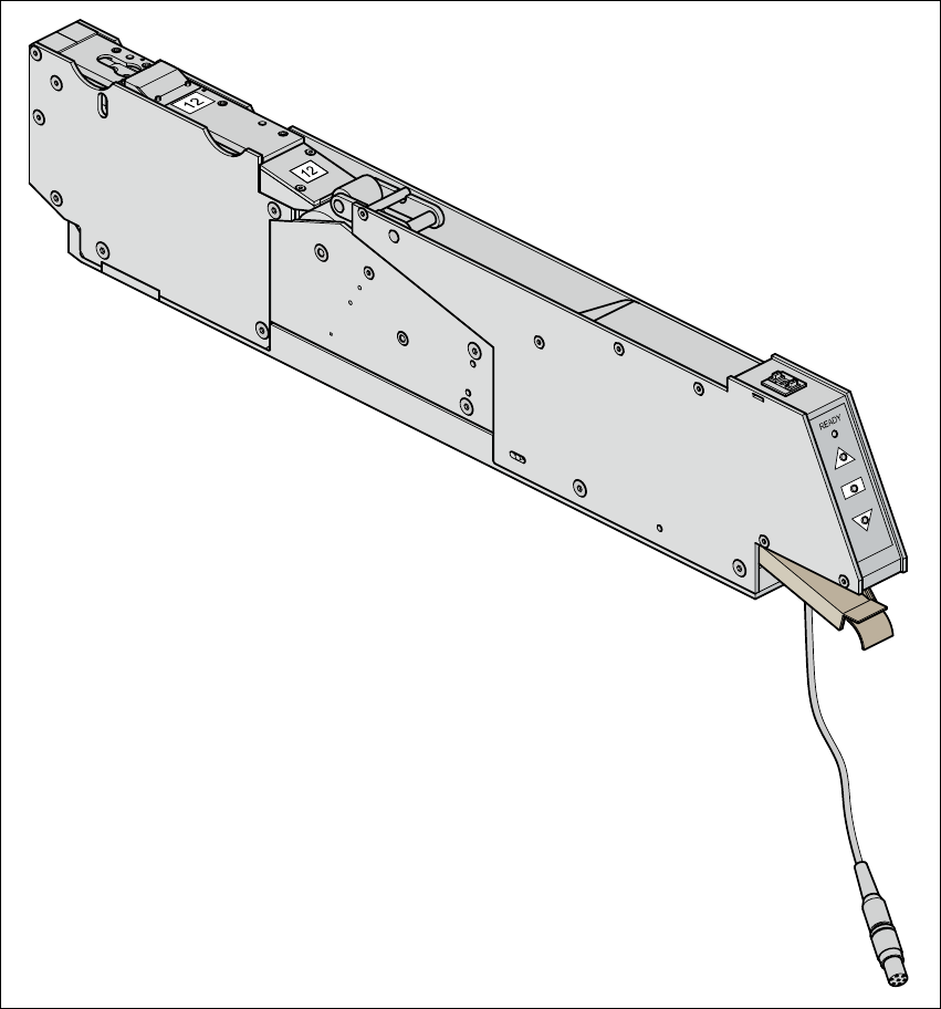
For placing bare dies, you will need the surf tape feeder module for feeding components. There
are versions of these feeder modules for 8-, 12- and 16 mm tapes.
6
Fig. 6.2 - 10 Surf tape feeder module
The surf tape feeder module can be ordered from Hover-Davis (www.hoverdavis.com). Handling
of the feeder module is described in the operating instructions for feeder modules.

User Manual SIPLACE CS 6 Component handling
Software Version SR.408.xx 03/2006 US Edition 6.2 Technical data for the S feeder modules
141
6.2.10.2 Technical data
6
6
6
6.2.10.3 Parameters for surf tape feeder modules
The parameters for the surf tape feeder module can be modified on the SIPLACE Pro computer.
Tape widths 8/12/16 mm
Recommended tape and component
sizes
8 mm: for 1 x 1 mm² - 2.3 x 2.3 mm² components
12 mm: for 2.3 x 2.3 mm² - 5 x 5 mm² components
16 mm: for 3.8 x 3.8 mm² - 9.5 x 9.5 mm² components
Packaging accuracy of the bare die on
the surf tape
Bare die size up to 2.3 x 2.3 mm²: +/- 100 µm, 6 σ
Bare die size over 2.3 x 2.3 mm²: +/- 200 µm, 6 σ
(related to the center of the pocket)
Required distance between the edges
of the bare dies to the tape pocket Min. 0.4 mm
Pusher needle Single or triple needle depending on the die size
Tape material Metric
Tape standard IEC 286-3, DIN-IEC-286, EIA 481, and JIS C 0806
Tape reel diameter 7" to 15"
Footprint of the feeder module 1 location on the component table
6 Component handling User Manual SIPLACE CS
6.2 Technical data for the S feeder modules Software Version SR.408.xx03/2006 US Edition
142
6.2.11 Dip module
6
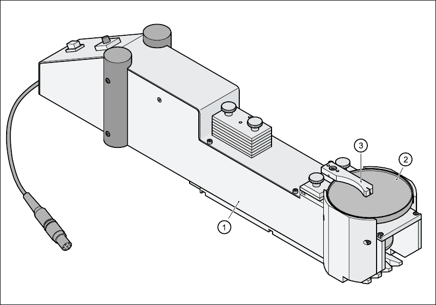
Fig. 6.2 - 11 Dip module
(1) Dip module
(2) Rotating plate
(3) Squeegee
6.2.11.1 Principle of dip fluxing
The dip module (item 1) is used to wet flip-chip and CSP components with flux or conductive ad-
hesive. The flux holder is a rotating plate (item 2) on which a thin film of flux (e.g. 40 µm) is created
with a squeegee (item 3). This method is particularly suitable for highly viscous (honey-like) fluxes.
The amount of flux required for the process is reduced to a minimum coating thickness since only
the undersides of the bumps have to be wetted.
The dip module is suitable for all placement heads. It is regarded as a standalone type of conveyor
by the set-up optimization. There is no limit to the number of dip modules at the individual loca-
tions.