00194086-01.pdf - 第45页
User Manual SIPLAC E CS 2 Operational safety Software Vers ion SR.408.xx 03/2006 U S Edition 2.5 Safety equipment 45 (12) Protective cov er swit ch (left, 003 21416-x x) (13) Main power switch (14) Protective con tactor …
2 Operational safety User Manual SIPLACE CS
2.5 Safety equipment Software Version SR.408.xx03/2006 US Edition
44
2.5.3 EMERGENCY STOP buttons, protective cover switches ...
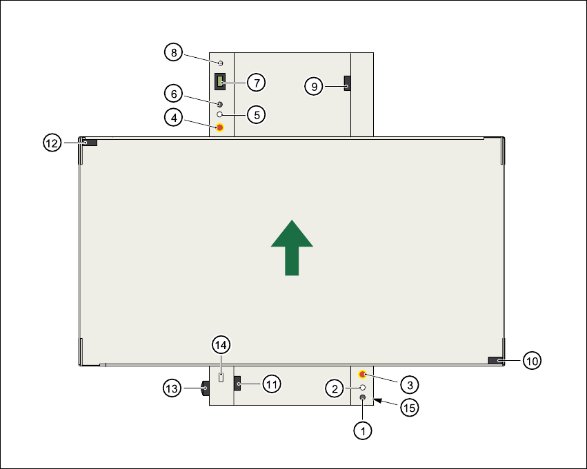
Fig. 2.5 - 4 Location of the buttons and protective contactor combination K1
2
(1) Stop button
(2) Start button
(3) EMERGENCY STOP button
(4) EMERGENCY STOP button
(5) Start button
(6) Stop button
(7) Component counter
(8) Key switch open: position 0 for normal operation
Key switch shut: position I for service purposes
(9) Protective cover switch (output conveyor, 00303617-xx)
(10) Protective cover switch (right, 00321417-xx)
(11) Protective cover switch (input conveyor, 00303614-xx)
User Manual SIPLACE CS 2 Operational safety
Software Version SR.408.xx 03/2006 US Edition 2.5 Safety equipment
45
(12) Protective cover switch (left, 00321416-xx)
(13) Main power switch
(14) Protective contactor combination K1 at the power supply unit
(15) Compressed air unit
2.5.3.1 Description of the functions
EMERGENCY STOP button
When the EMERGENCY STOP button is pressed (item 3 or item 4. in Fig. 2.5 - 4), the motor
voltage to the gantry axes is switched off. The gantry axes are no longer powered, and thus are
not dangerous.
PLEASE NOTE
Placement is interrupted and can then either be continued or canceled once the system is working
correctly again. 2
Protective cover switch
If one of the protective covers is opened (see item 9, 10, 11 or 12 in Fig. 2.5 - 4), the gantry axes
will stop immediately. They are no longer powered, and thus are not dangerous.
Key-operated switch:
If the key switch (item 8 in Fig. 2.5 - 4) is closed (position I), the star can still be paced at low
speed while the protective covers are open. The gantry axes are no longer powered, and thus
are not dangerous.
PLEASE NOTE
The key switch remains open for normal mode, i.e. in the 0 position. 2
WARNING
The protective covers must only be opened, with the key switch closed (position I), by appropri-
ately qualified and trained personnel. 2
2.5.3.2 Status messages and the action required
The following displays may appear in placement mode. If they appear, carry out the action spec-
ified in the third column.
2 Operational safety User Manual SIPLACE CS
2.5 Safety equipment Software Version SR.408.xx03/2006 US Edition
46
2
2.5.4 Safety circuits
The SIPLACE automatic placement system has a safety circuit which is monitored by the protec-
tive contactor combination K1. The protective contactor combination is contained in the power
supply unit (see item 14 in Fig. 2.5 - 4
).
WARNING
Automatic placement systems from the SIPLACE family are powered with 3 x 400 VAC (3 x 208
VAC for the U.S.A. version) ± 5 %, 50/60 Hz main power voltage.
This means that some parts of the system carry potentially lethal voltages - even when switched
off at the main power switch. Death, serious injury or considerable damage may result if these au-
tomatic placement systems are handled incorrectly.
Always follow the applicable accident prevention and DIN regulations (particularly EN 60204,
part 1) and the applicable regulations in your own country.
The guard over the power supply must ONLY be opened by appropriately qualified and trained
personnel. 2
The protective safety combination K1 monitors the EMERGENCY-STOP circuits, the safety loops
for the component trolleys or protective cover switches and the enable software signal.
K1 is triggered if any of these functions fail. The main power voltage to the heavy current trans-
former that supplies the gantry axis motors, the star motor, the lifting tables and the used tape
cutter will be interrupted. The DP and Z axes of the placement heads continue to be supplied
with 30 V. The next diagram illustrates the various statuses of K1 and their effects on the axes
and the PCB conveyor components.
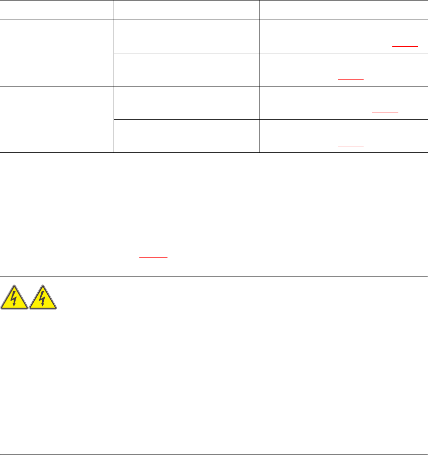
Status Display on screen Action required
EMERGENCY STOP but-
ton pressed
EMERGENCY STOP pressed ...
Machine stopped. Release button
Release the pressed EMERGENCY
STOP button (item 3 or 4 in Fig. 2.5 - 4
)
Press start button Press the white start button
(item 2 or 5 in Fig. 2.5 - 4
)
Protective cover open Close the cover Close the protective cover
(item 9, 10, 11 or 12 in Fig. 2.5 - 4
)
Press start button Press the white start button
(item 2 or 5 in Fig. 2.5 - 4
)
Tab. 2.5 - 1 Screen display when the EMERGENCY STOP button is pressed or the protective cover is open