00194086-01.pdf - 第81页
User Manual SIPLAC E CS 3 Technical data Software Vers ion SR.408.xx 03/2006 U S Edition 3.8 6-segment Collect&Place head 81 3.8 6-segment C ollect&Pla ce head 3.8.1 Structure of the 6- segment Collect&Place …

3 Technical data User Manual SIPLACE CS
3.7 Gantries Software Version SR.408.xx03/2006 US Edition
80
3.7.3 Technical data for the X axis
3
3.7.4 Structure of the Y axis
The Y-axis essentially consists of the following main modules:
– Y-axis three-phase AC servomotor
– Y-axis toothed belt
– Y-axis guide system
– Y-axis measuring system
Each Y-axis is driven by a three-phase AC servomotor. An anti-crash circuit prevents the travers-
ing paths of the gantries meeting.
3.7.5 Technical data for the Y-axis
3
Drive Three-phase AC servomotor/toothed belt
Maximum speed 2.5 m/sec.
Traversing path 620 mm
Distance measuring system Metal linear scale
Scale length 646 mm
Resolution 2.5 µm
Drive Three-phase AC servomotor/toothed belt
Maximum speed 2.5 m/sec.
Traversing path 910 mm
Distance measuring system Metal linear scale
Scale length 970 mm
Resolution 2.5 µm
User Manual SIPLACE CS 3 Technical data
Software Version SR.408.xx 03/2006 US Edition 3.8 6-segment Collect&Place head
81
3.8 6-segment Collect&Place head
3.8.1 Structure of the 6-segment Collect&Place head with standard component
vision camera
3
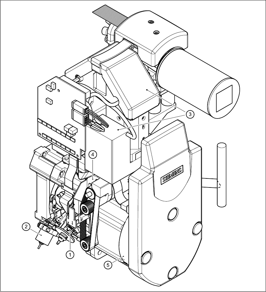
Fig. 3.8 - 1 Structure of the 6-segment Collect&Place head with standard component vision camera - part 1
(1) Star with 6 sleeves (2) Motor for "Reject" valve adjustment drive
(3) Component vision camera (4) Z-axis drive
(5) Star motor
3 Technical data User Manual SIPLACE CS
3.8 6-segment Collect&Place head Software Version SR.408.xx03/2006 US Edition
82
3
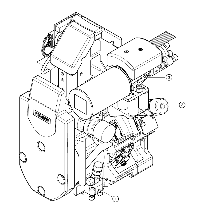
Fig. 3.8 - 2 Structure of the 6-segment Collect&Place head with standard component vision camera - part 2
3
(1) Forced air valve
(2) Turning station
(3) Vacuum generator