00194086-01.pdf - 第146页
6 Component handling User Manual SIPLACE C S 6.3 Component trolley Software Version SR. 408.xx03/2006 US Edition 146 It is easy to fit. Use three screws DIN 91 2, M8x20 (item 3) to fix the co mpressed ai r supply (item 2…
User Manual SIPLACE CS 6 Component handling
Software Version SR.408.xx 03/2006 US Edition 6.3 Component trolley
145
6.3.2 Tape container
Reels up to 19" (483 mm) in diameter may be used. Insert them into the separating plates as
shown in Fig. 5.3 - 2
.
PLEASE NOTE 6
We recommend that you use spindles if the tape reel diameter exceeds 15" (381 mm). This will
ensure that the feeder modules operate reliably. 6
6
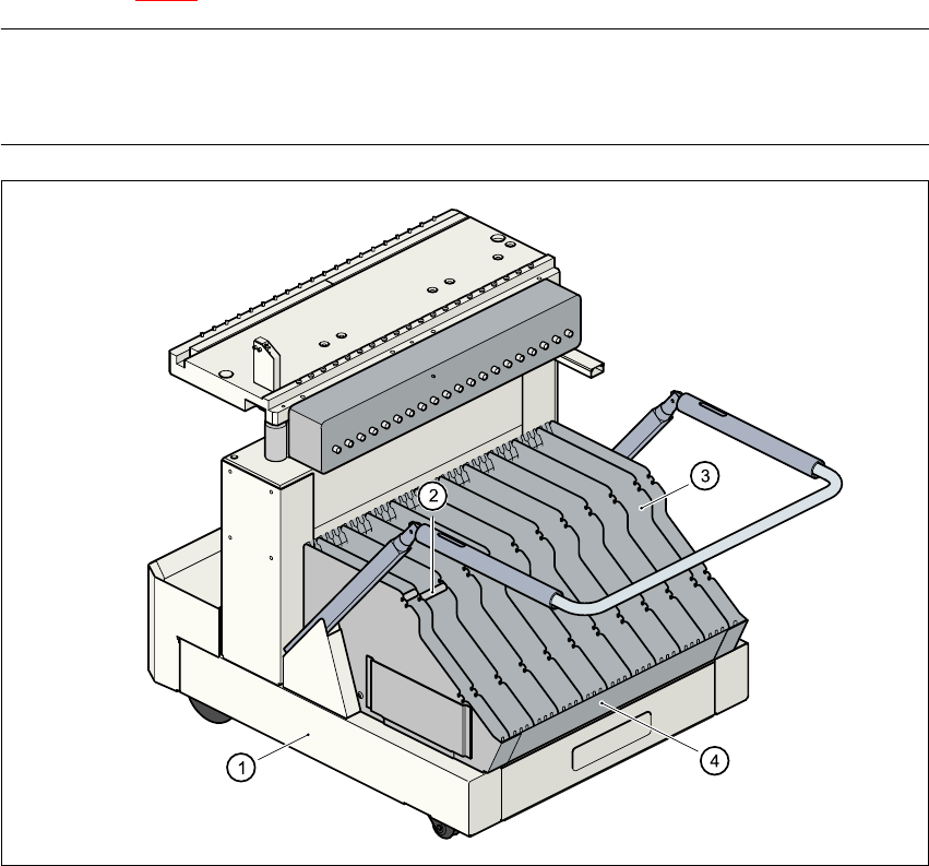
Fig. 6.3 - 2 Component trolley with tape container
(1) Component trolley
(2) Spindles
(3) Separating plate
(4) Tape container
6.3.3 Compressed air supply for bulk case feeder modules
Bulk case feeder modules require compressed air in order to work. A compressed air supply for
bulk case feeder modules is therefore available as an option.
6 Component handling User Manual SIPLACE CS
6.3 Component trolley Software Version SR.408.xx03/2006 US Edition
146
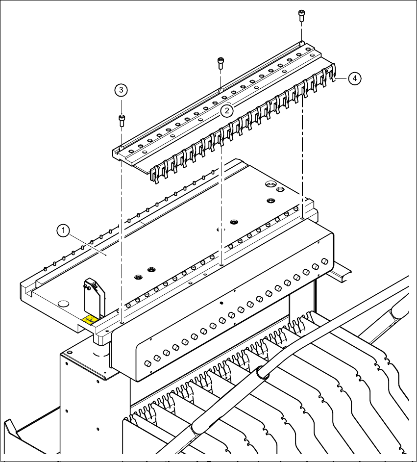
It is easy to fit. Use three screws DIN 912, M8x20 (item 3) to fix the compressed air supply (item
2) to the component feeder table (item 1). The compressed air supply has retaining clips (item 4)
on the back. They fix the bulk case feeder modules to the component table and thus ensure a per-
fect compressed air supply.
6
Fig. 6.3 - 3 Compressed air supply for bulk case feeder modules
(1) Component table
(2) Compressed air supply for bulk case feeder modules
(3) Screw DIN 912, M8x20
(4) Retaining clamp
User Manual SIPLACE CS 6 Component handling
Software Version SR.408.xx 03/2006 US Edition 6.3 Component trolley
147
6
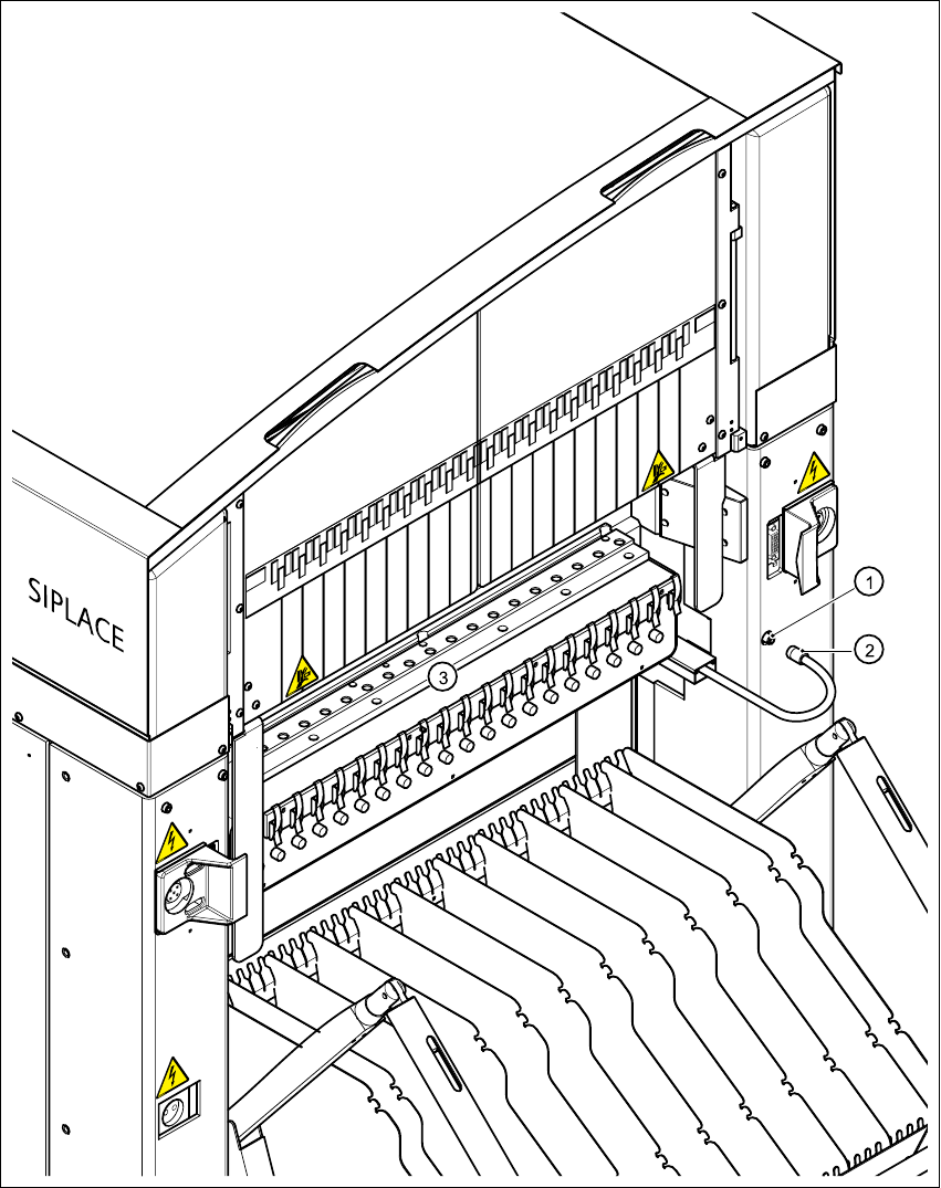
Fig. 6.3 - 4 Connecting the compressed air supply for bulk case feeders
6
(1) Coupling connector for compressed air
(2) Coupling socket with supply hose
(3) Compressed air distributor for bulk case feeder modules