00194086-01.pdf - 第86页
3 Technical data User Manual SIPLACE CS 3.9 Vision modules Software Version SR.408.xx03/2006 US Edition 86 3.9.3 PCB vis ion camera (st andard camera) 3.9.3.1 S tructure 3 Fig. 3.9 - 2 PC B vision camera (standard camera…
User Manual SIPLACE CS 3 Technical data
Software Version SR.408.xx 03/2006 US Edition 3.9 Vision modules
85
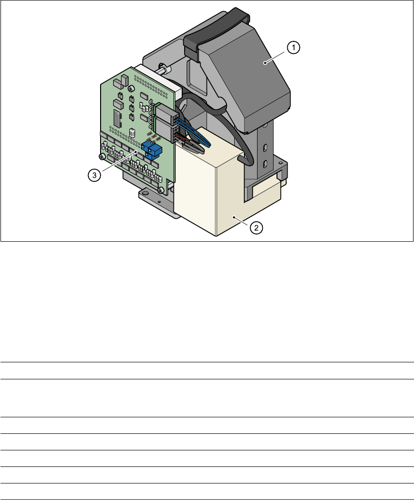
3.9.2 Component vision camera (standard camera) on the 6-segment
Collect&Place head
3.9.2.1 Structure
3
Fig. 3.9 - 1 Component vision camera on the 6-segment Collect&Place head
(1) Component camera, lens and illumination
(2) Camera amplifier
(3) Illumination control
3.9.2.2 Technical data
3
Max. component dimensions 0.6 mm x 0.3 mm to 18.7 mm x 18.7 mm
Range of components 0201 to PLCC44
including BGA, µBGA, flip-chip, TSOP, QFP
PLCC, SO to SO32, DRAM
Min. lead pitch 0.5 mm
Min. bump pitch 0.35 mm
Min. ball/bump diameter 0.2 mm
Field of vision 24 mm x 24 mm
Method of illumination Front-lighting (3 levels, programable as required)
3 Technical data User Manual SIPLACE CS
3.9 Vision modules Software Version SR.408.xx03/2006 US Edition
86
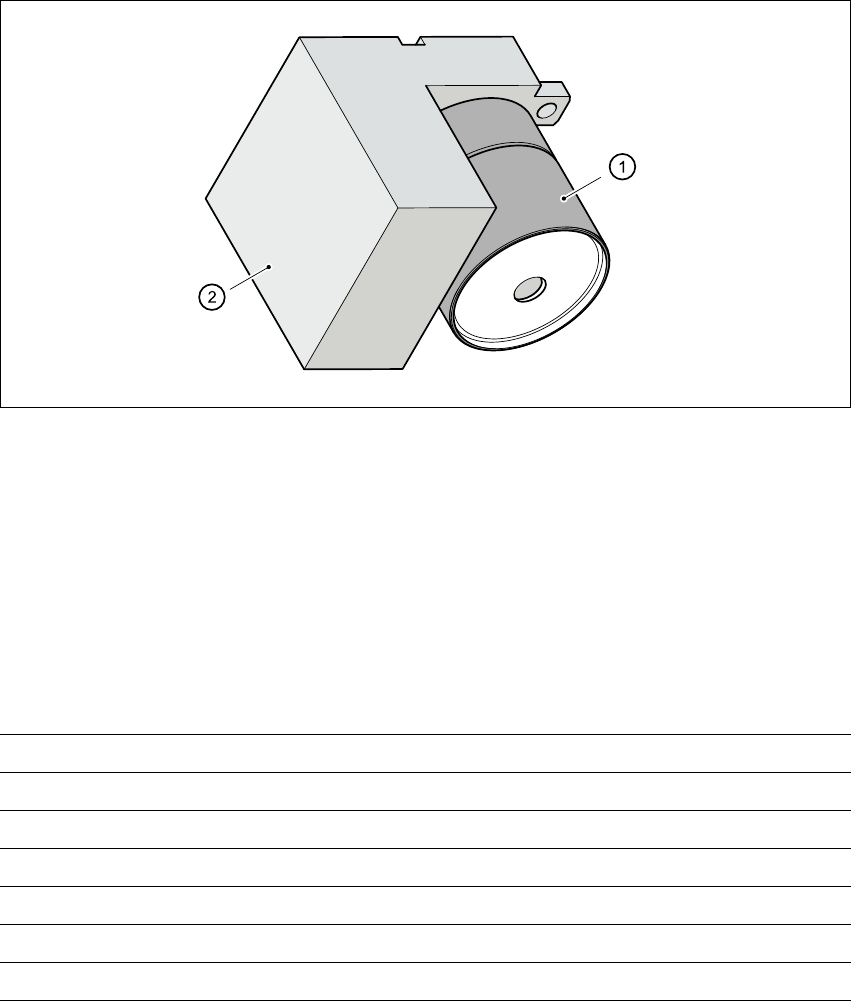
3.9.3 PCB vision camera (standard camera)
3.9.3.1 Structure
3
Fig. 3.9 - 2 PCB vision camera (standard camera)
(1) PCB camera, lens and illumination
(2) Camera amplifier
3.9.3.2 Technical data - PCB vision camera
3
Fiducials Up to 3 (subpanels and multiple panels)
Local fiducials Up to 2 per PCB (may be of different types)
Library size Up to 255 fiducial types - system fiducials ≥ 249
Image processing Geometric alignment
Method of illumination Front-lighting
Detection time per fiducial/bad fiducial 0.4 s
Field of vision 5.7 mm x 5.7 mm

User Manual SIPLACE CS 3 Technical data
Software Version SR.408.xx 03/2006 US Edition 3.10 Nozzle changer for the 6-segment Collect&Place head
87
3.10 Nozzle changer for the 6-segment Collect&Place
head
3.10.1 Overview
The placement system is supplied as standard with two Collect&Place heads. As an option, a
nozzle changer can be installed for each Collect&Place head. This enables the nozzle configura-
tion to be changed quickly, thus allowing the Collect&Place head to be quickly adapted to the
needs of the placement process.
The nozzle changer consists of at least one, and up to five magazines, each with twelve nozzle
garages (see Fig. 3.10 - 1
). The magazines are seated on a common support. Each magazine is
centered using two parallel pins and fixed in place with a spring hook.
3.10.2 Technical data
3
Nozzle changer for the 6-segment Collect&Place head
Dimensions (length x width x height) 673 mm x 74 mm x 75 mm
Number of nozzle garages Min. 6 / max. 30
Nozzle types 9 xx
Time required to open and close the locking plate < 200 ms
Capacity of the reject bin Approx. 50 nozzles
Pneumatic system Compressed air line 0.53 MPa (5.3 bar)