00194086-01.pdf - 第145页
User Manual SIPLAC E CS 6 Component handling Software Vers ion SR.408.xx 03/2006 U S Edition 6.3 Component trolley 145 6.3.2 T ape conta iner Reels up to 19" (4 83 mm) i n diameter m ay be u sed. Inse rt them i nto …
6 Component handling User Manual SIPLACE CS
6.3 Component trolley Software Version SR.408.xx03/2006 US Edition
144
6.3 Component trolley
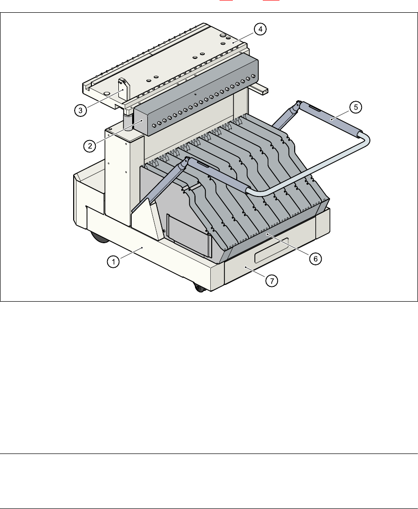
6.3.1 Structure
The component trolley consists essentially of a chassis, a component feeder table on which the
feeder is mounted, a communication unit, a tape container and a waste container. Docking the
component trolley in or out is described in Section 5.8
, page 120 onwards.
Fig. 6.3 - 1 Component trolley
(1) Component trolley
(2) Communication unit
(3) Control button for raising the component feeder table
(4) Component feeder table
(5) Handle for locking and lowering the component feeder table
(6) Tape container
(7) Waste tape container
NOTE ON OPERATIONAL SAFETY
All component trolleys must be docked on the machine in order to operate it. If they are not, the
machine stays in EMERGENCY STOP status. The placement process is interrupted.
User Manual SIPLACE CS 6 Component handling
Software Version SR.408.xx 03/2006 US Edition 6.3 Component trolley
145
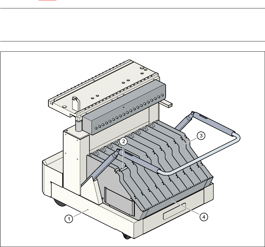
6.3.2 Tape container
Reels up to 19" (483 mm) in diameter may be used. Insert them into the separating plates as
shown in Fig. 5.3 - 2
.
PLEASE NOTE 6
We recommend that you use spindles if the tape reel diameter exceeds 15" (381 mm). This will
ensure that the feeder modules operate reliably. 6
6
Fig. 6.3 - 2 Component trolley with tape container
(1) Component trolley
(2) Spindles
(3) Separating plate
(4) Tape container
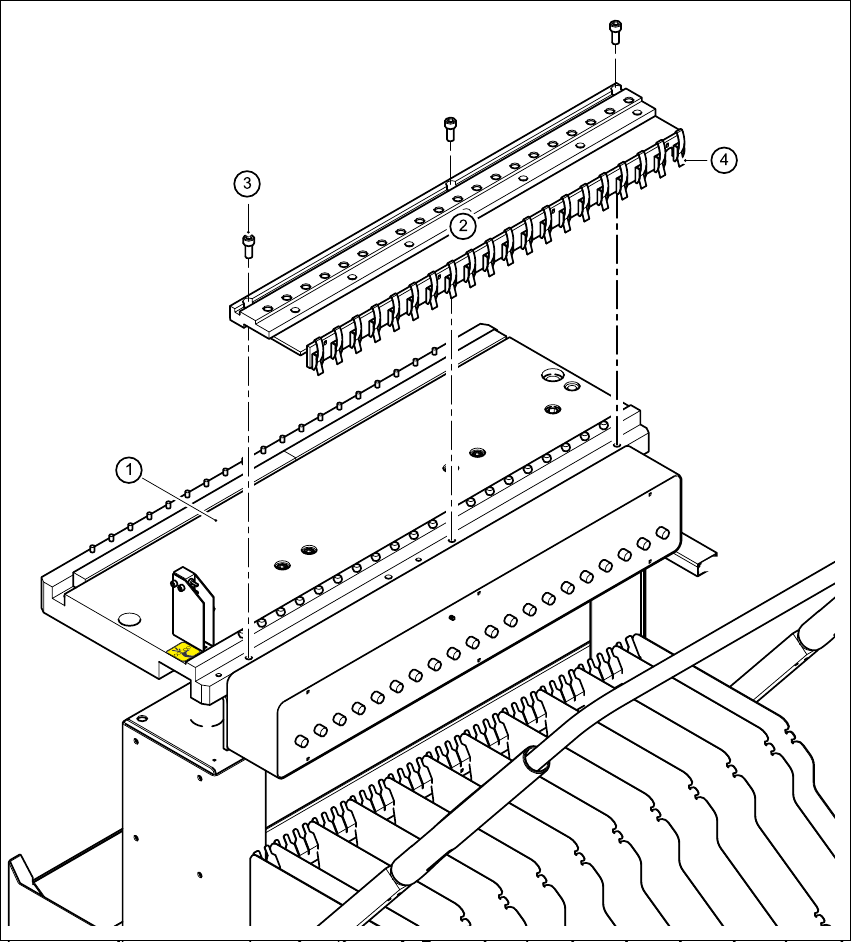
6.3.3 Compressed air supply for bulk case feeder modules
Bulk case feeder modules require compressed air in order to work. A compressed air supply for
bulk case feeder modules is therefore available as an option.
6 Component handling User Manual SIPLACE CS
6.3 Component trolley Software Version SR.408.xx03/2006 US Edition
146
It is easy to fit. Use three screws DIN 912, M8x20 (item 3) to fix the compressed air supply (item
2) to the component feeder table (item 1). The compressed air supply has retaining clips (item 4)
on the back. They fix the bulk case feeder modules to the component table and thus ensure a per-
fect compressed air supply.
6
Fig. 6.3 - 3 Compressed air supply for bulk case feeder modules
(1) Component table
(2) Compressed air supply for bulk case feeder modules
(3) Screw DIN 912, M8x20
(4) Retaining clamp