ACT - Accuracy Check Tool User Manual.pdf - 第141页
ACT - Accurac y Check Tool / Us er Man ual 06/2015 Edition 53 Figure 4-31: Dialog box: Enter PC B (example SIPLACE D1) ► Now ins ert the boar d into the input s ection (see also se ction 4.2.2 ). The board gets plac ed a…
ACT - Accuracy Check Tool / User Manual 06/2015 Edition
52
Figure 4-29: Dialog box after setting ACT mode. Display: ACT icon
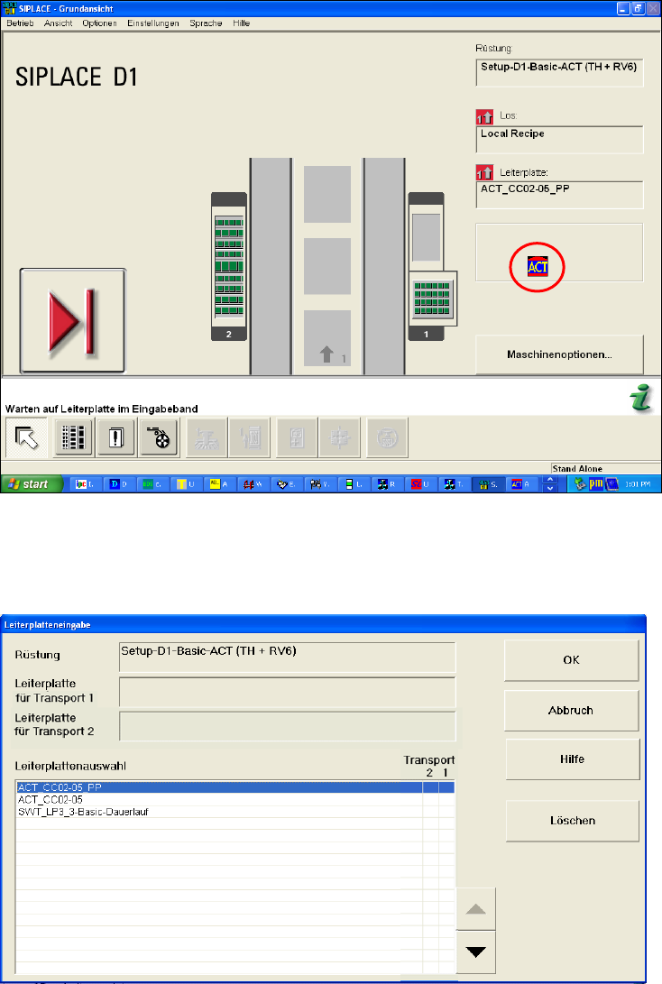
The Leiterplatteneingabe (Enter PCB) dialog box is opened (Figure 4-30).
► Select the ACT board.
Figure 4-30: Dialog box: Enter PCB (example SIPLACE D1)
The Leiterplatteneingabe (Enter PCB) dialog box is opened (Figure 4-31).
► Select the ACT board.
► Select the conveyor lane.
► Confirm your entry with OK.
ACT - Accuracy Check Tool / User Manual 06/2015 Edition
53
Figure 4-31: Dialog box: Enter PCB (example SIPLACE D1)
► Now insert the board into the input section (see also section 4.2.2).
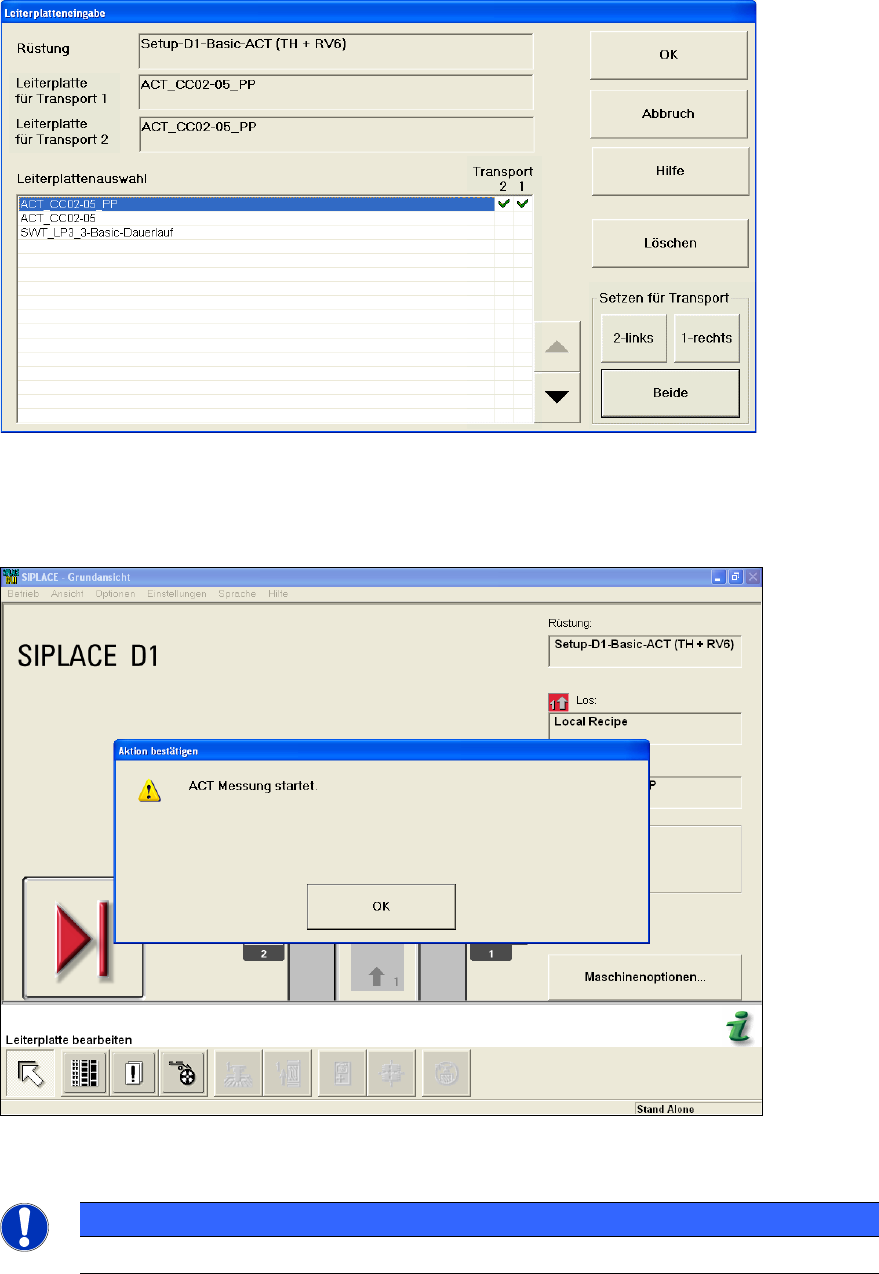
The board gets placed and then the measurement starts automatically.
Figure 4-32: Message for ACT measurement (example SIPLACE D1)
NOTICE
The machine should not be operated during the measurement!
A dialog box opens in which the current measurement operation is displayed. The fiducials that are
currently being measured are displayed.
ACT - Accuracy Check Tool / User Manual 06/2015 Edition
54
Example of measurement operation with the ceramic components Cerampads:
Figure 4-33: Example of measurement window with Cerampads
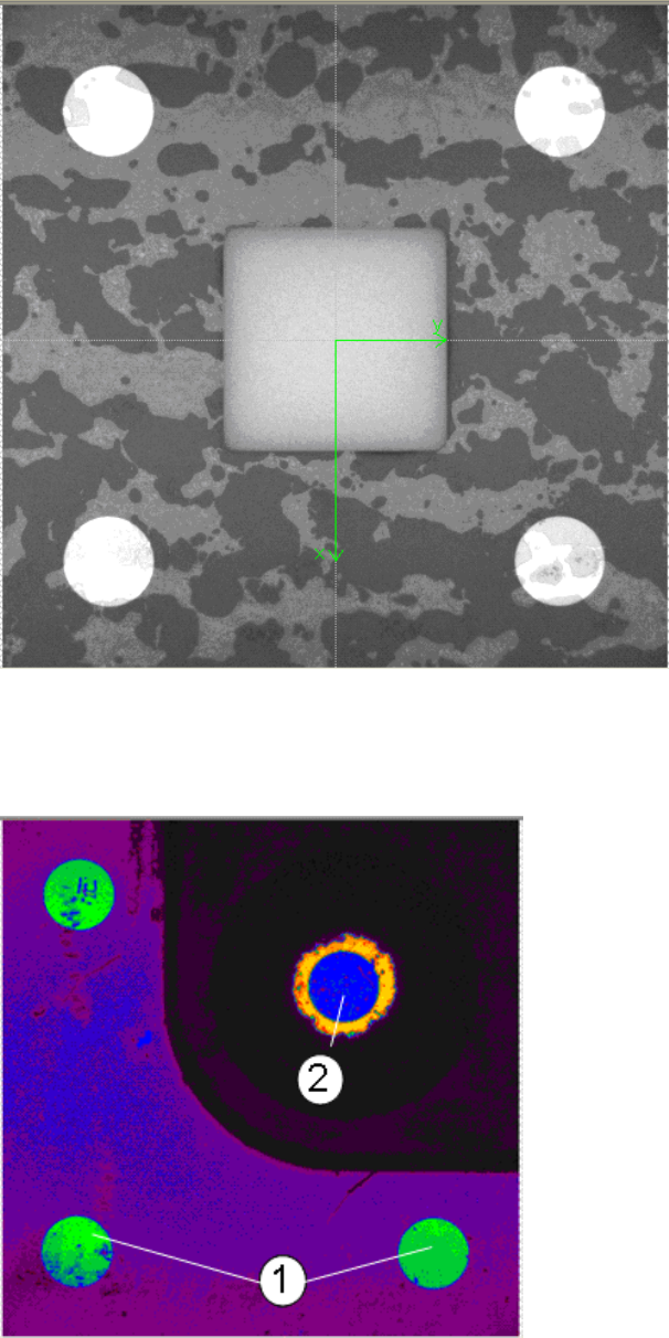
Example of measurement operation with glass components:
Figure 4-34: View of measurement window with glass components (pseudo color view)
Key:
(1) Fiducials on the ACT plate (2) Fiducials on the glass component