00196770-04_VD_SSW_705_04_SP2_DE_EN.pdf - 第13页
Station Software 705.04 SP2 / Version De scription Ausgabe 06/2012 Edition 5.2 Digital camera systems Digital CCD cameras are used as the camera system s. 5.2.1 Component cameras All heads are equipped wit h the standard…
Station Software 705.04 SP2 / Version Description Ausgabe 06/2012 Edition
5 Hardware specifications
5.1 Supported feeder types
The following feeders are supported by the 705.04 SP2 station software version:
– 8 mm – 88 mm X-feeder
– 2x8 mm X-feeder
– 4 mm X-feeder
– 16 mm XN-feeder
– 104 mm X-feeder
– Surftape AX (8 mm, 12 mm, 16 mm)
– Arbitrary Carrier X (only X-series)
– Carrier X (XTH) (only X2, X3, X4 in setup area 2 and 4)
– Carrier SX (only SX1/SX2 with Twin Head and CPP head)
– FFI feeders:
HanSan LED feeder
Top Engineering LED feeder
Data IO RoadRunners
– IPTE Multi Stick Feeder:
IPTE multi stick 60 AX
IPTE multi stick XL80 AX
– Stick feeder with X-adapter
– Label feeder with X-adapter
– Reject conveyor with X-adapter
– Dip module for X-tables (LDU_X)
– MTC2 (only X2, X3, X4 in setup area 2 and 4)
– WPC5 (only SX1/SX2)
– WPC6 Non Stop Module (only SX1/SX2)
– Splice sensor X-feeder
12
Station Software 705.04 SP2 / Version Description Ausgabe 06/2012 Edition
5.2 Digital camera systems
Digital CCD cameras are used as the camera systems.
5.2.1 Component cameras
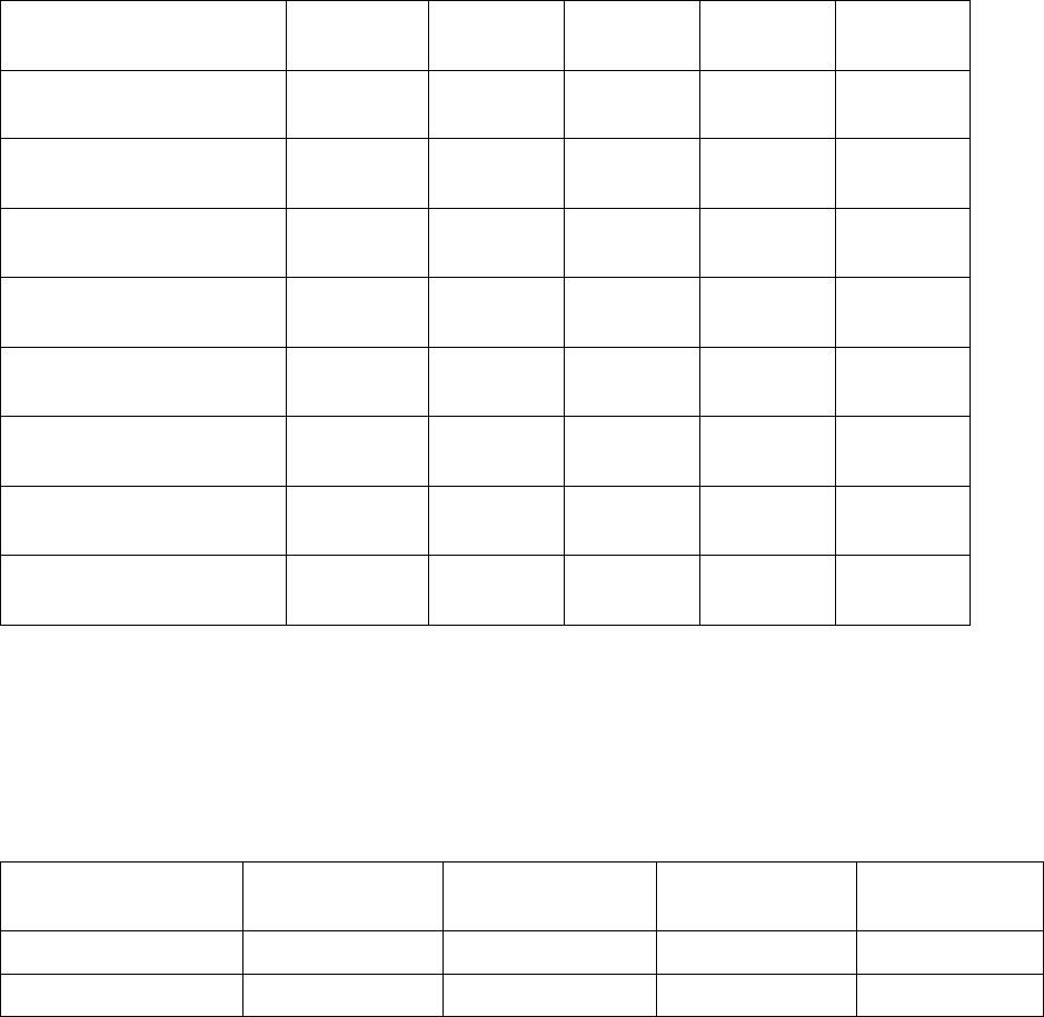
All heads are equipped with the standard camera listed below. High-resolution cameras are
additionally available for Twin Head and CPP.
Component camera Camera
type
CPP
type
C&P20A
head
Twin
Head
C&P12
head
C&P
6 x 6 mm digital
23
-
9 (default) - -
C&P
18.7 x 18.7 mm digital
28
9 (optional) - - 9 (default)
C&P
27 x 27 mm digital
29
9 (optional) - - -
C&P
27 x 27 mm digital
30
9 (default) - - 9 (optional)
C&P
16 x 16 mm digital
38
9 (optional) - - -
Stat. P&P
16 x 16 mm digital
2
)
25
- - 9 (optional) -
Stat. P&P
55 x 45 mm digital
2)
33
9 (optional)
1)
- 9 (default) -
Stat. P&P
32 x 32 mm digital
36
9 (optional) - 9 (optional) -
Table 5-1: Component cameras
1)
Only together with CPP head, with which components up to a height of 11.5 mm can be placed.
2)
Is not supported on the SIPLACE X4I placement machine.
5.2.2 Board cameras
Board camera Camera type SIPLACE X-series SIPLACE SX-
series
SIPLACE DX-
series
28 digital 34 9 (default) 9 (default) 9 (default)
Multicolor 28 digital 24 9 (optional)
Table 5-2: Board cameras
13
Station Software 705.04 SP2 / Version Description Ausgabe 06/2012 Edition
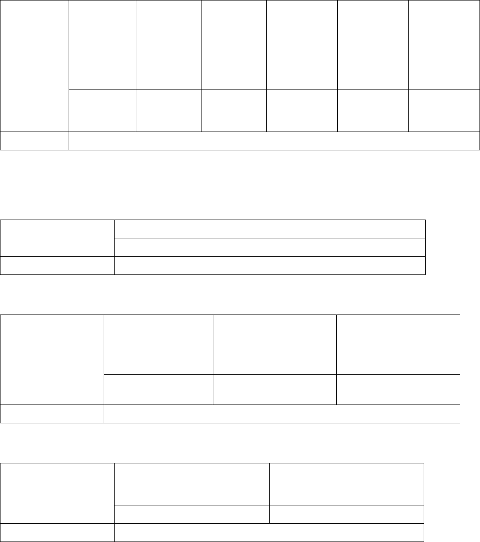
5.3 Component range
With type 28
component
camera
(C&P 18,7 x
18,7 mm
digital)
With type
29
component
camera
(C&P 27 x
27 mm
digital)
With default
type 30
component
camera
(C&P 27 x
27 mm
digital)
With type 38
component
camera (C&P
16 x 16 mm
digital)
With type 33
component
camera (Stat.
P&P 55 x 45
mm digital)
With type 36
component
camera (Stat.
P&P 32 x 32
mm digital)
Component
range for
CPP head
0402
through 18.7
x 18.7 mm
01005
*)
through 27
x 27 mm
01005
through 27
x 27 mm
01005
through 16 x
16 mm
(0603)
through
55 x 45 mm
0603 through
32 x 32 mm
Nozzle types 20xx, 28xx
Table 5-3: Component range CPP head
*)
If components with an edge length between 0.19 and 0.26 mm are taught, a warning is displayed,
that the placement quality may be less than specified.
With default type 23 component camera (C&P 6 x 6 mm digital)
Component range for
C&P20A head
01005 through 6 x 6 mm
Nozzle types 10 xx, 11 xx, 12 xx
Table 5-4: Component range C&P20A head
With type 25
component camera
(Stat. P&P 16 x 16
mm digital)
With default type 33
component camera (Stat.
P&P 55 x 45 mm digital)
With type 36 component
camera (Stat. P&P 32 x
32 mm digital)
Component range
for Twin Head
0201 through 16 x 16
mm
0402 through 55 x 45 mm 0603 through 32 x 32 mm
Nozzle types 5 xx (standard), 4 xx + adapter, 8 xx + adapter, 9xx + adapter
Table 5-5: Component range Twin Head
With default type 28 component
camera (C&P 18,7 x 18,7 mm
digital)
With type 30 component camera
(C&P 27 x 27 mm digital)
Component range for
C&P12 head
0402 through 18.7 x 18.7 mm 0201
*)
through 27 x 27 mm
Nozzle types 30xx
Table 5-6: Component range C&P12 head
*)
0201 components can only be placed restrictively.
14