Portal_Manual_1.2.1_Rev_H-1.pdf - 第44页
Portal PVA Revisio n H ( 2018 ) 44 of 93 The end effecto r may have di spense heads , each of which has a needle. Wh en a needle is replaced , or the machine is s tarted , th e needles sh ould be ca librated. When the ma…
Portal
PVA
Revision H (2018)
43 of 93
8.4.2 Operator Defined Needle Calibration
For operator defined needle calibration you must use the trackball to define the
coordinate system to the position of a specific needle or dispense head. If the needle is
in the correct position, this procedure is not necessary.
1. The head moves to a calibration point (specified in the main program).
2. When at the calibration position use the trackball to put the needle tip in
correct position as it relates to a calibration point (such as cross-hairs).
3. Select the “CAL” function key to start this procedure if a needle needs to be
replaced during operation.
8.4.3 Sensor Defined Needle Calibration
The Needle Calibration Unit (NCU) is referenced from the home position on the gantry.
The start positions for each head to enter the NCU are referenced from the cross-hair
mark on the top of the NCU. The coordinates are defined for each head using thru-beam
sensors in the NCU.
• Z is always calibrated first in a downward motion into the Z sensor.
• The X and Y coordinates are then calibrated from this position in reference to
the positioning of the NCU in the work area. The needle moves into the next
sensor (X or Y) finding the first coordinate, then moves to the opposite side of
the sensor and finds a second coordinate.
• The calibration routine then calculates the center of the needle average of the
first and second coordinates and redefines the new position accordingly. This
sequence is repeated for the remaining axis.
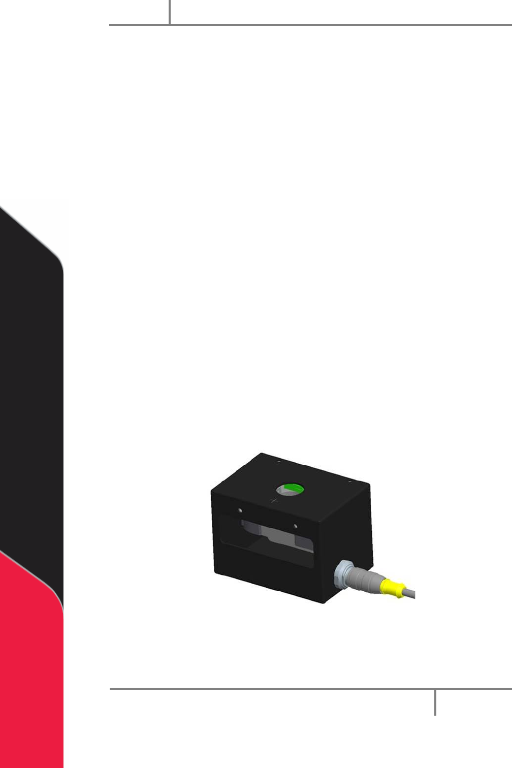
Figure 29: Needle Sensor Calibration Block
Portal
PVA
Revision H (2018)
44 of 93
The end effector may have dispense heads, each of which has a needle. When a needle
is replaced, or the machine is started, the needles should be calibrated. When the
machine is in this mode, it automatically moves to a pre-set calibration point.
Figure 30: Sensor Defined Needle Calibration
Each head on the gantry will have a set reference position. The operator can select the
head, and move the gantry to its related position. When at the preset point, the
operator must physically reposition the dispense needle to make sure the calibration is
correct.
NOTE: If you have a calibration plate, each valve tip should align with the
crosshair center point. If it does not, physically move the valve until it does.
This is only for the mechanical alignment of the head assembly.
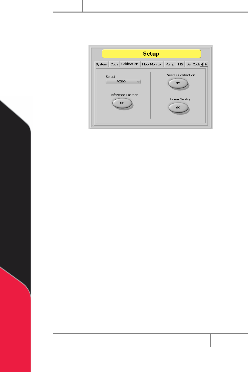
1. In Setup mode, select the Calibration tab.
2. Select the “Select Valve” dropdown menu to change the active valve.
3. Select the Reference Position “GO” button to move the selected valve to the
related reference position. This is useful when maintenance is done that might
change the alignment of the gantry (to replace a valve after a head collision).
4. Select the Home Gantry “GO” button to home the system. The machine will
NOT go to the standby point until the operator exits Setup mode.
5. Select the Needle Calibration “GO” button to start the needle calibration
procedure. Do the steps shown on the screen to calibrate the needle.
Portal
PVA
Revision H (2018)
45 of 93
8.5 Pump (Optional)
The pump configuration can be changed under the “Pump” tab in Setup mode as
shown. Refer to the Optional Equipment folder of your electronic manual for more
information.
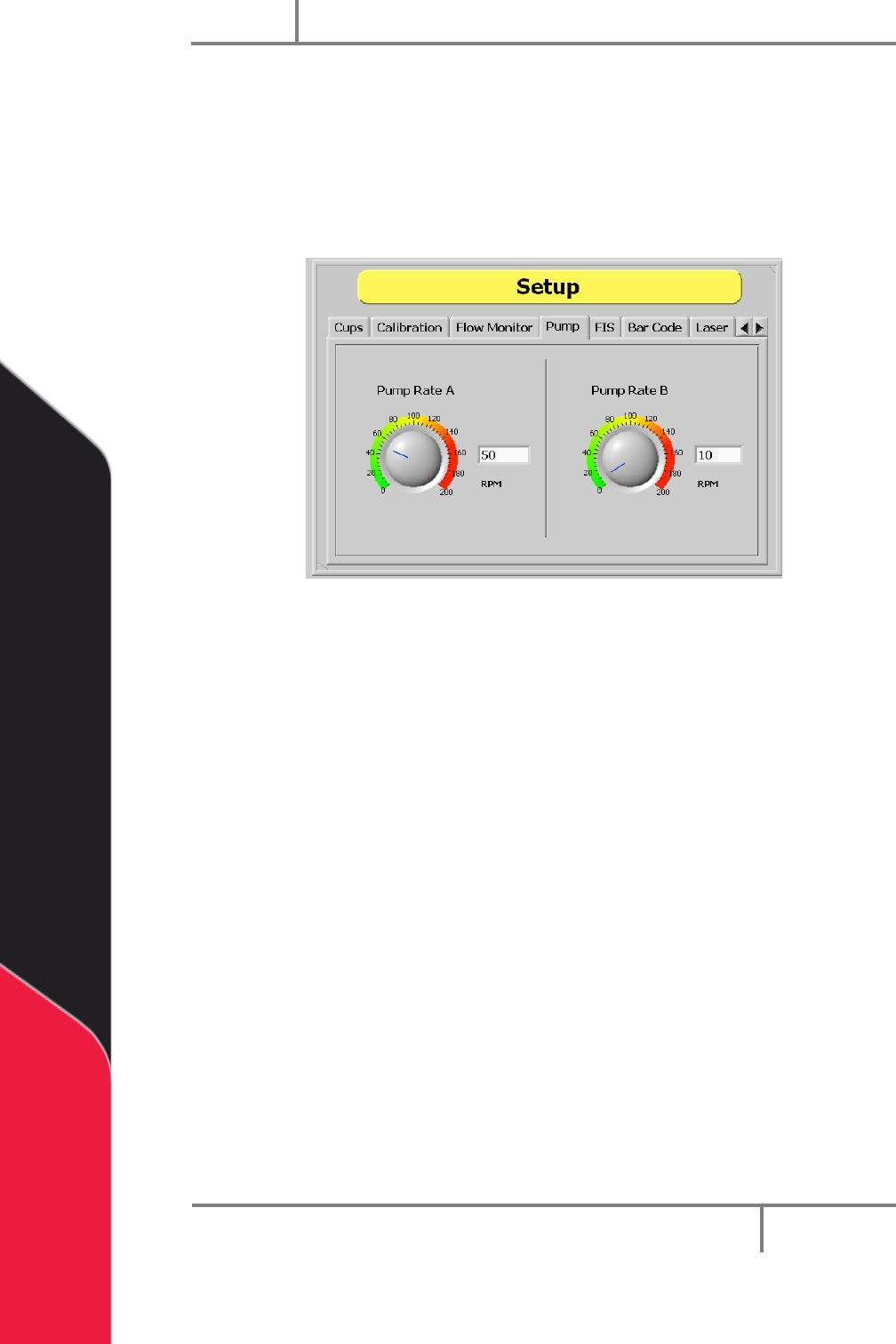
1. In Setup mode, select the “Pump” tab.
Figure 31: Pump Setup
2. To change the pump rate, type the value in the “Pump Rate A (RPM)” or “Pump
Rate B (RPM)” box or use the cursor to move the dial to the necessary position.
NOTE: The stated RPM is of the motor, not the pump. In general, the ratio will
be 20:1, 50:1 or 100:1 depending on the system. This in can also be found in
the Setup tree. Refer to your valve manual for more information.