SOM-1613-002.pdf - 第10页
9 Tg0780-PM-SO 0209-001 5. Setup Operation • Sheet Composition *1 Devices Device Name : The following names represent the items that can be set up. X/Y T able Chute Width L Conveyor Width R Conveyor Width P .C.B. Support…
8 Tg0780-PM-SO
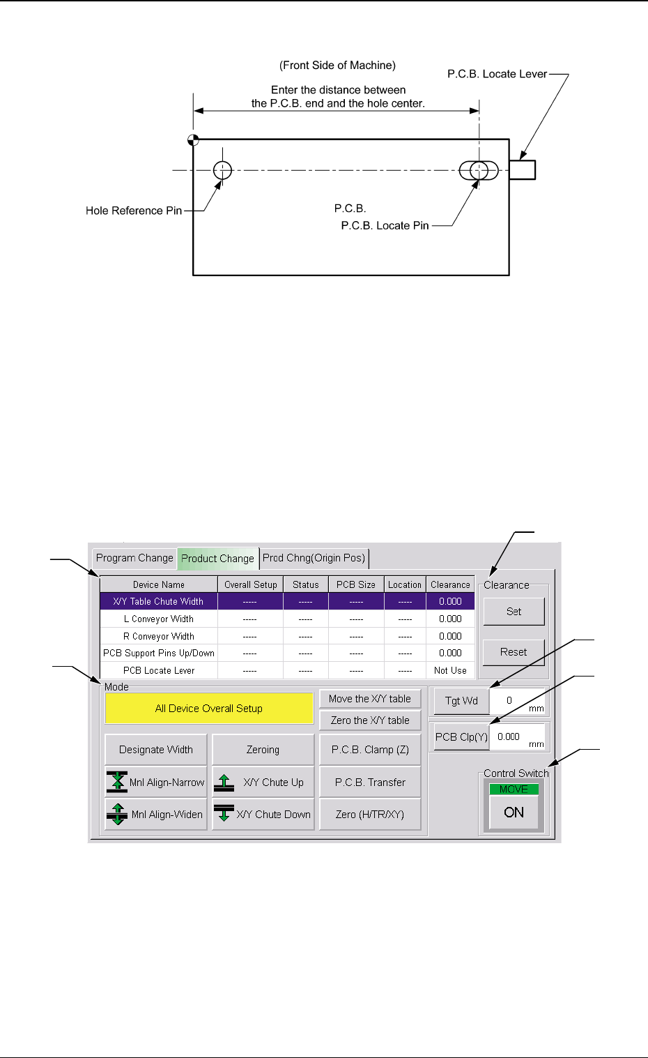
Reference Point: "Hole"
5.2 Overall Setup Operation after Selection of the
[Product Change] Tab
When the [Product Change] tab is pressed at the "PROGRAM
CHANGE" submenu window, the following tab sheet appears.
0312-002
5. Setup Operation
Fig. 4-3
Fig. 4-2
*3
*5
*6
*4
*2
*1

9 Tg0780-PM-SO0209-001
5. Setup Operation
• Sheet Composition
*1 Devices
Device Name : The following names represent the items that can
be set up.
X/Y Table Chute Width
L Conveyor Width
R Conveyor Width
P.C.B. Support Pins Up/Down
P.C.B. Locate Lever
Overall Setup: ON or OFF appears in the text box.
Status : When the [ON] button (*6) is pressed, the setup
operation starts and the status of each device is
indicated.
"Ready" : The setup operation is completed and the
device is located at the position "P.C.B.
Size (Width) + Clearance''.
"Not Ready" : The devices are located at the position
"P.C.B. Width + Clearance" but the cur-
rent position is not under control.
'' -----'' : The current position or program is indefi-
nite.
'' -----'' (red) : ''Disable" is set for the setup data.
P.C.B. Size : Displayed are the P.C.B. sizes (widths) in the cur-
rent pattern program data.
When the current pattern program is indefinite,
''-----'' appears.
Location : The currently managed widths appear in the text
boxes.
"-----" appears when the current location is indefi-
nite or is not managed.
When a device is selected for the setup operation, the background
color of the line turns blue.
*2 Mode
A setup mode can be selected.
The background color of the selected button turns yellow.

10 Tg0780-PM-SO0209-001
5. Setup Operation
*3 Clearance
This data is used to give some leeway to the chute and conveyor
widths.
The actual widths become ''P.C.B. Size (Width) + Clearance''.
*4 [Tgt Wd] Button
When this button is pressed, the "Tgt Wd" edit window opens.
Enter a numerical value and press the [Set] button. The entered
value is set as a target one.
*5 [PCB CIp (Y)] Button
When this button is pressed, the "PCB Clp (Y)" edit window opens.
Enter a numerical value and press the [Set] button. The entered
value is set as a value for Y clamping.
*6 Control Switch
When the [ON] button entitled "MOVE" is pressed, the setup
operation starts.
All Devices Overall Setup Operation
(1) Press the [AII Device Overall Setup] button (*2).
(2) Enter numerical values as clearance data (*3) for both chute and
conveyor widths and press the [Clearance Reset] button.
(3) Press the [ON] button in the "Control Switch" group box and then
the [ENABLE] button on the operation panel in two seconds. The
all device overall setup operation starts and the foIIowings are
indicated in the ''Status" text box (*1) of each device.
"Ready" : The setup operation is completed and the devices
are located at the position "P.C.B. Width + Clear-
ance".
"Not Ready" : The devices are located at the position "P.C.B.
Width + Clearance" but the current position is not
under control.
"-----" : The current position or program is indefinite.
"-----" (red) : "Disable" is set for the setup data.
When the current pattern program is indefinite, zeroing operation
is implemented and the automatic setup operation is performed
continuously.