SOM-1613-002.pdf - 第7页
6 Tg0780-PM-SO Parts for Positioning of "Hole Reference" and "Outline Reference" Depending on the selected positioning method, use the following parts. T able 2 0312-002 4. Items to be Checked before …
5 Tg0780-PM-SO
Reference Pin
P.C.B. Locate Pin
#
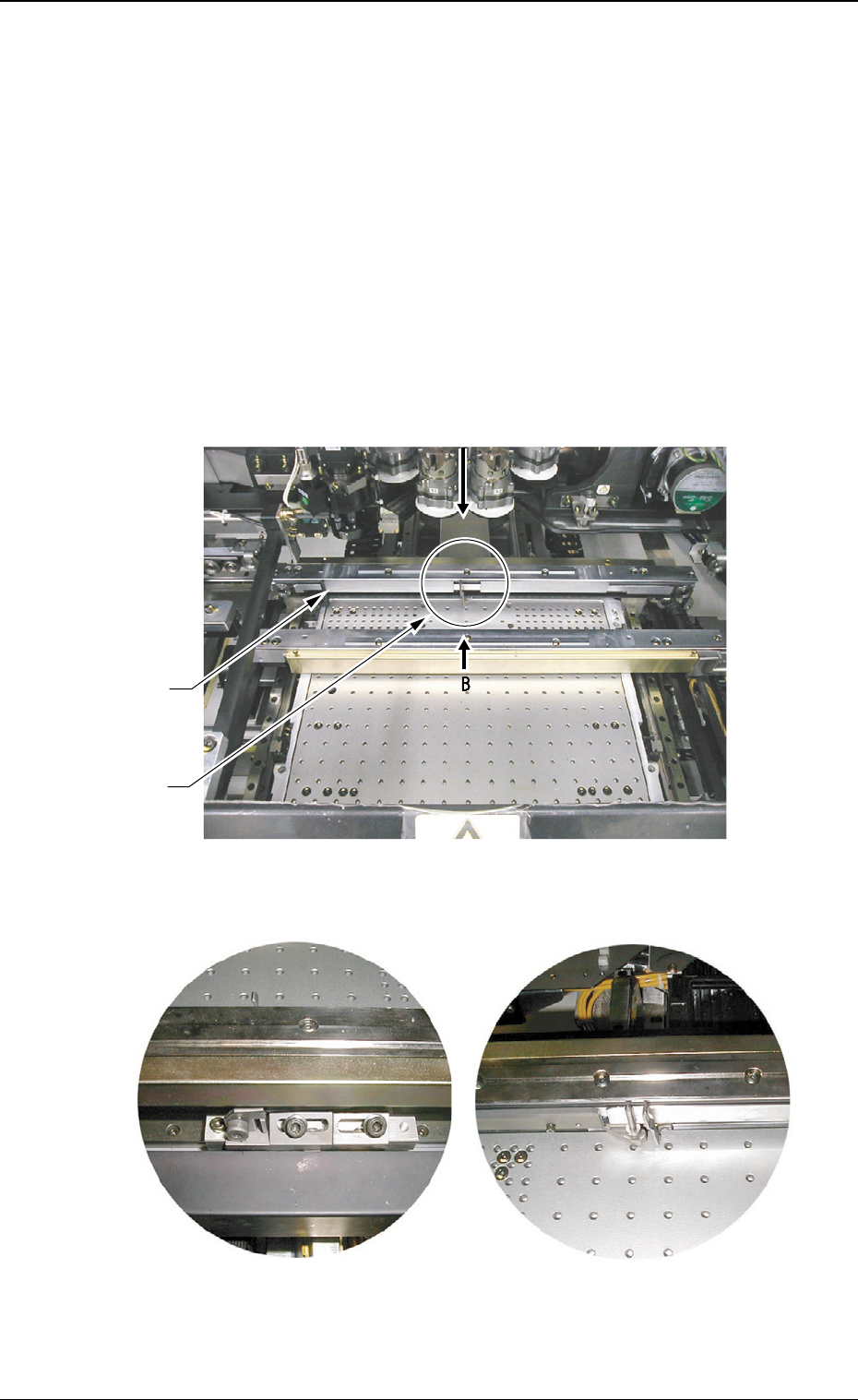
4. Items to be Checked before Setup Operation
• Before zeroing or set-up operation, check that there is no obstacle
(structure) on the backup base of the X/Y table.
• Especially when a support pin or a jig P.C.B. is located in the range of
approx. 20 mm away from the fixed chute, it hinders the setup opera-
tion, causing an error.
• When each device is zeroed to its origin, the P.C.B. locate pin and the
P.C.B. locate lever move toward the direction of the maximum P.C.B.
size.
0209-001
4. Items to be Checked before Setup Operation
Fig. 1-2 View A
Fig. 1-1
Fig. 1-3 View B
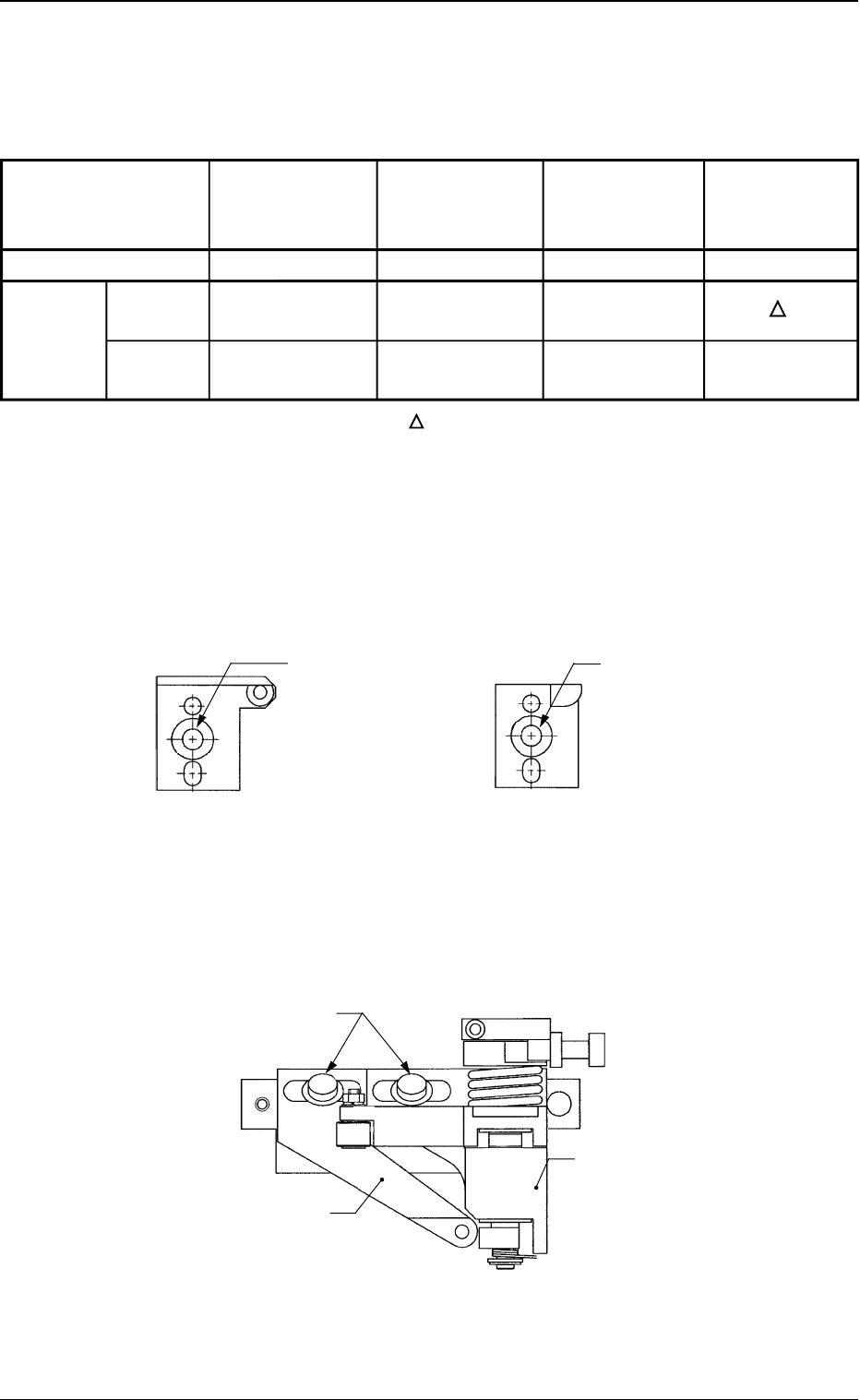
6 Tg0780-PM-SO
Parts for Positioning of "Hole Reference" and "Outline Reference"
Depending on the selected positioning method, use the following parts.
Table 2
0312-002
4. Items to be Checked before Setup Operation
Fig. 2-1 Hole Reference Pin
(Reference Side)
Fig. 2-2 Outline Pilot Pin
(Reference Side)
Fig. 2-3 P.C.B. Locate Pin and P.C.B. Locate Lever
Flanged Bolt with
Hexagon Socket
Head (M5L16)
Flanged Bolt with
Hexagon Socket
Head (M5L16)
{:Usable
××
××
×:Not Usable :Usable depending on the condition
• Use a flanged bolt with hexagon socket head (M5L16) to attach a
P.C.B. locate pin.
P.C.B. Locate Lever
P.C.B. Locate Pin
Flanged Bolt with Hexagon
Socket Head (M5L16)
Part Name
Fig. No.
Hole
Positioning Reference
Method Outline
Reference
Hole Reference
Pin
(Reference Side)
Fig. 2-1
{
××
××
×
Outline Pilot
Pin
(Reference Side)
Fig. 2-2
××
××
×
{
P.C.B. Locate
Pin
Fig. 2-3
{
××
××
×
P.C.B.
Locate Lever
Fig. 2-3
{
7 Tg0780-PM-SO
*1
0312-002
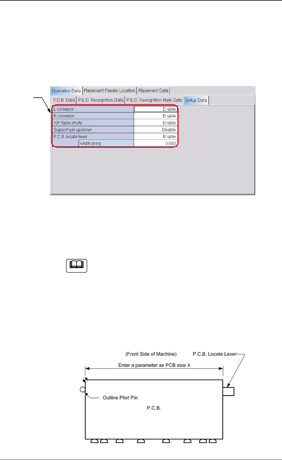
5. Setup Operation
*1 Setup Data
Set whether or not the setup data for each device is set. Select
"Enable" or "Disable" for each device.
When the setup operation is performed for the P.C.B.
locate pin, be sure to enter a parameter in the " Width
[mm]" data box of the label "P.C.B. locate lever" in ac-
cordance with the selected positioning method "Hole" or
"Outline".
Unless a correct parameter is entered, the P.C.B. locate
pin cannot be positioned to have the correct width.
Reference Point: "Outline"
5. Setup Operation
5.1 Setting of Setup Parameters
When the [Setup Data] tab is pressed on the "Operation Data" tab
sheet, the following tab sheet appears.
Fig. 3
Fig. 4-1
Note