SOM-1613-002.pdf - 第6页
5 Tg0780-PM-SO Reference Pin P .C.B. Locate Pin # 4. Items to be Checked before Setup Operation • Before zeroing or set-up operation, check that there is no obstacle (structure) on the backup base of the X/Y table. • Esp…
4 Tg0780-PM-SO0312-002
1. Scope
When a program change is made, the P.C.B. locate pin / P.C.B.
locate lever can be adjusted automatically, shortening the machine
setup time.
2. Specifications
Table 1
1. Scope
Description
• The P.C.B. locate pin / P.C.B. locate lever can be adjusted
automatically.
The overall setup operation interlocked with the program
change operation is implemented.
• Increments of 0.1 mm (Resolution: 0.003125 mm/pulse)
3. Precautionary Measures for Setup Operation
• When each device is zeroed to its origin, the P.C.B. locate lever width
becomes the maximum P.C.B. size (338.5 mm). Check that the P.C.B.
locate lever does not touch anything when it is widened to the maxi-
mum extent.
• Check that there is no P.C.B. on the X/Y table.
• Check that there is no P.C.B. support pin on the X/Y table.
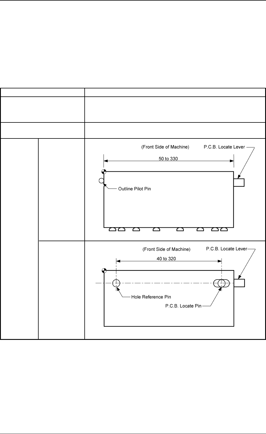
Reference
Point: ''Outline''
Reference
Point: ''Hole''
3. Operating
Range
Item
1. Function
2. Unit of P.C.B. Locate Pin
Movement
5 Tg0780-PM-SO
Reference Pin
P.C.B. Locate Pin
#
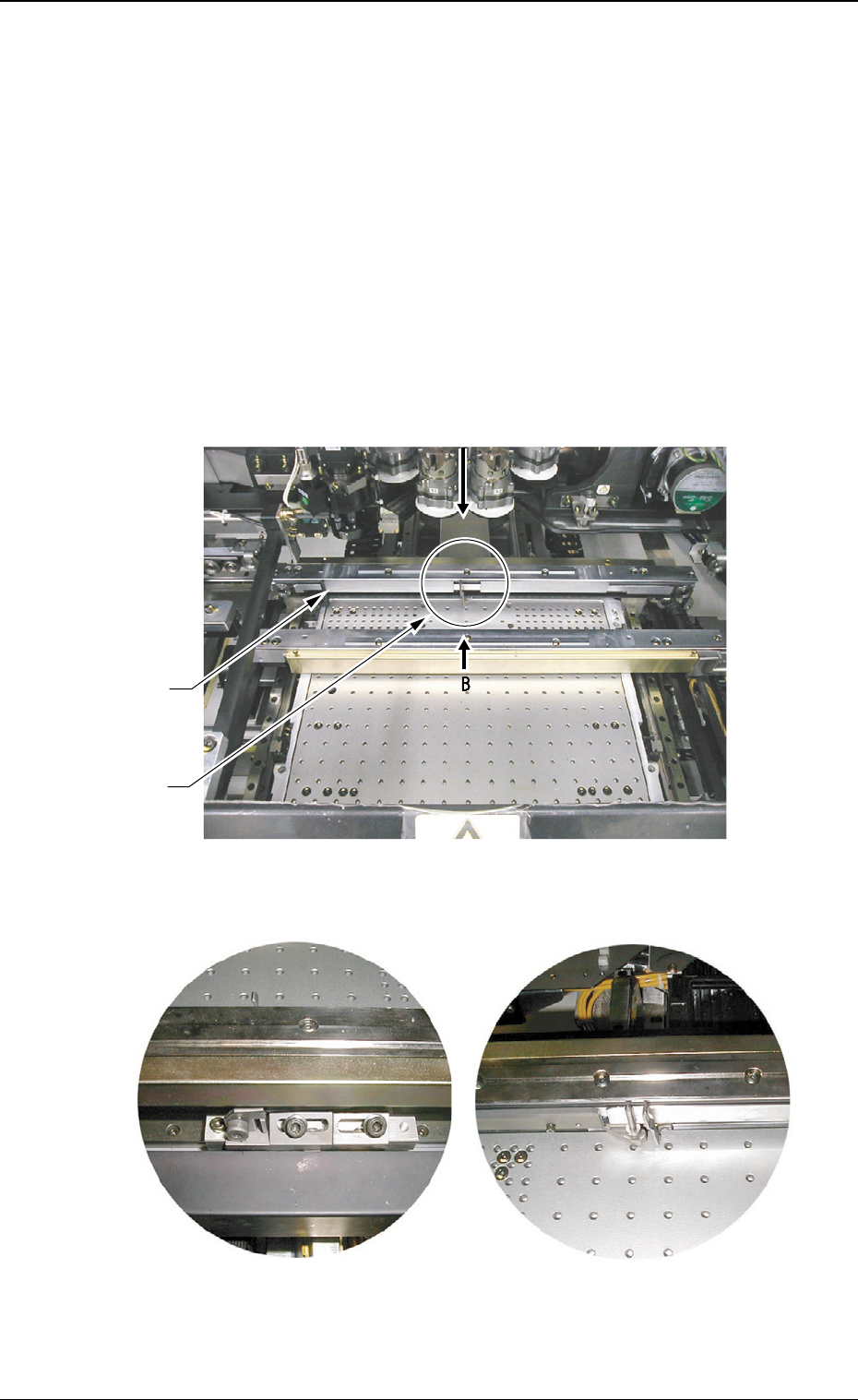
4. Items to be Checked before Setup Operation
• Before zeroing or set-up operation, check that there is no obstacle
(structure) on the backup base of the X/Y table.
• Especially when a support pin or a jig P.C.B. is located in the range of
approx. 20 mm away from the fixed chute, it hinders the setup opera-
tion, causing an error.
• When each device is zeroed to its origin, the P.C.B. locate pin and the
P.C.B. locate lever move toward the direction of the maximum P.C.B.
size.
0209-001
4. Items to be Checked before Setup Operation
Fig. 1-2 View A
Fig. 1-1
Fig. 1-3 View B
6 Tg0780-PM-SO
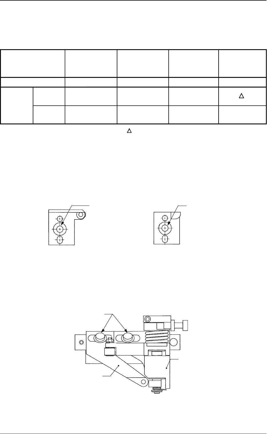
Parts for Positioning of "Hole Reference" and "Outline Reference"
Depending on the selected positioning method, use the following parts.
Table 2
0312-002
4. Items to be Checked before Setup Operation
Fig. 2-1 Hole Reference Pin
(Reference Side)
Fig. 2-2 Outline Pilot Pin
(Reference Side)
Fig. 2-3 P.C.B. Locate Pin and P.C.B. Locate Lever
Flanged Bolt with
Hexagon Socket
Head (M5L16)
Flanged Bolt with
Hexagon Socket
Head (M5L16)
{:Usable
××
××
×:Not Usable :Usable depending on the condition
• Use a flanged bolt with hexagon socket head (M5L16) to attach a
P.C.B. locate pin.
P.C.B. Locate Lever
P.C.B. Locate Pin
Flanged Bolt with Hexagon
Socket Head (M5L16)
Part Name
Fig. No.
Hole
Positioning Reference
Method Outline
Reference
Hole Reference
Pin
(Reference Side)
Fig. 2-1
{
××
××
×
Outline Pilot
Pin
(Reference Side)
Fig. 2-2
××
××
×
{
P.C.B. Locate
Pin
Fig. 2-3
{
××
××
×
P.C.B.
Locate Lever
Fig. 2-3
{