SOM-1653-001.pdf - 第19页
Tg0756-PM-SO 0206-001 18 5.2 Example of Pattern Program Creation (2) Creation of Operation Data • P .C.B. Data T able 5 Placement mode P .C.B. positioning reference P .C.B. locate Unit P .C.B. B.B.R. Mode Stan dard Mark …
Tg0756-PM-SO0206-001 17
5.2 Example of Pattern Program Creation
5.2 Example of Pattern Program Creation
Repetitive Patterns (Unit P.C.B. B.B.R. Function Enabled)
Described below are the typical examples of data creation.
The preparation example is described as based on TIM-X100R.
For TIM-X100F, the P.C.B. reference is located on the front
right.
(1) Information on Pattern Program Creation
• P.C.B. Size and Packaged Posture & IDs of Components
Set the same parameters as in "Volume 3: Programming and Ma-
chine Data, Section 2, 3.1 Single Pattern" in the instruction manual
for the main machine.
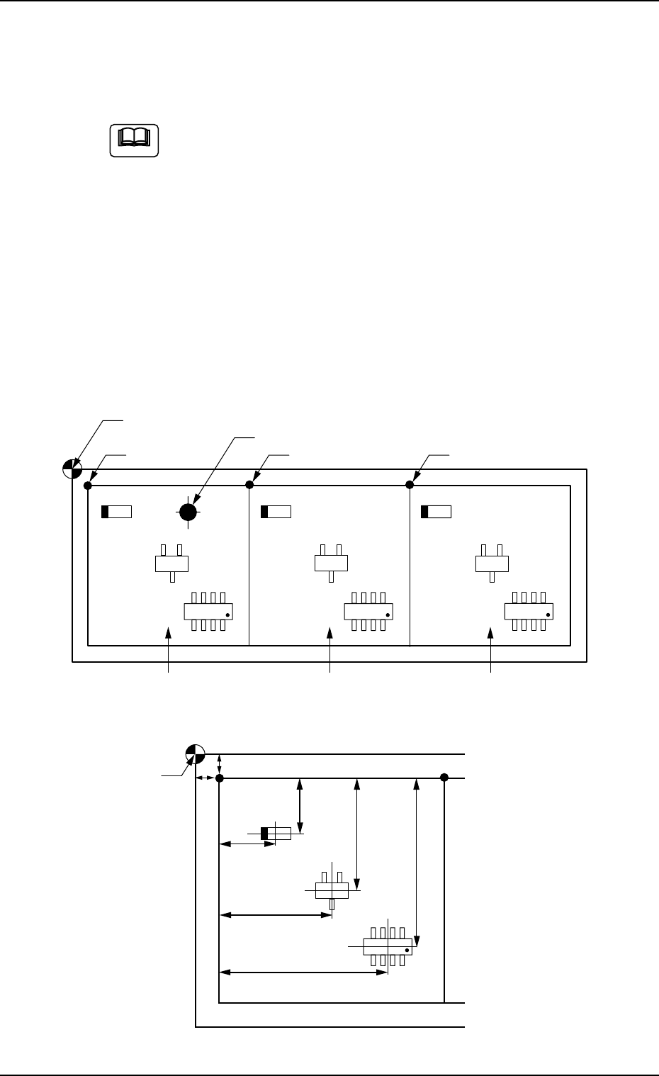
• Placement Coordinates and Angles (Z=Theta)
Note
Fig. 20 General View
Fig. 21 Pattern 1 (Magnified View)
Placement Coordinate Reference Point
Location of Bad Mark (BX1, BY1)
(OX1, OY1) (OX2, OY2) Pattern Origin (OX3, OY3)
Pattern 1 Pattern 2 Pattern 3
Placement Coordinate
Reference Point
X
3
Y
3
X
2
Y
2
X
1
Y
1
OY
1
OX
1
Tg0756-PM-SO0206-001 18
5.2 Example of Pattern Program Creation
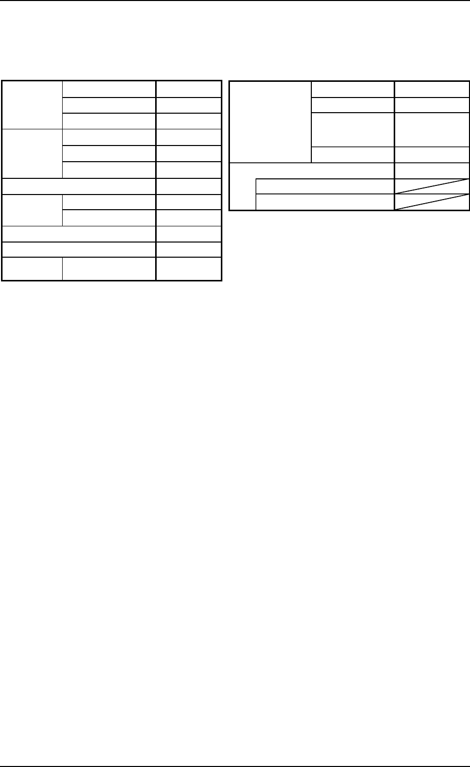
(2) Creation of Operation Data
• P.C.B. Data
Table 5
Placement mode
P.C.B. positioning reference
P.C.B.
locate
Unit P.C.B. B.B.R.
Mode Standard
Mark Image Dark (E/NR)
Component
prechuck
Disable
Sequence Bad Mark
Overall P.C.B. B.B.R. Disable
X (Horizontal)
Y (Vertical)
P.C.B. size
P.C.B.
origin offset
X (Horizontal)
Y (Vertical)
T (Thickness)
X (Horizontal)
Y (Vertical)
Z=Theta
P.C.B. height offset
Pre-Placed
cmpnt
thikness
335.00 [mm]
255.00 [mm]
1.6 [mm]
+00.000 [mm]
+00.000 [mm]
+00°000′
+00.000 [mm]
0.00 [mm]
0.00 [mm]
Placement
Rear Left
Outline
P.C.B. top
P.C.B. bottom
Datum
• P.E.C. Recognition Data
Set "Disable" in the "P.E.C. recognition function" text box.
Do not set any parameter in the other text boxes.
• P.E.C. Recognition Mark Data
Do not create this data.
• Setup Data
Create this data when the automatic setup function should be used.
(3) Creation of Placement Feeder Location Data
Set the same parameters as in "Volume 3: Programming and Ma-
chine Data, Section 2, 3.1 Single Pattern" in the instruction manual
for the main machine.
Tg0756-PM-SO0206-001 19
5.2 Example of Pattern Program Creation
Note
(4) Creation of Placement Data (P-data) U01
• Unit Control
Set the same parameters as in "Volume 3: Programming and Ma-
chine Data, Section 2, 3.1 Single Pattern" in the instruction manual
for the main machine.
• Unit P.C.B. B.B.R.
Set "Disable" in this text box.
Do not set any parameter in the other text boxes.
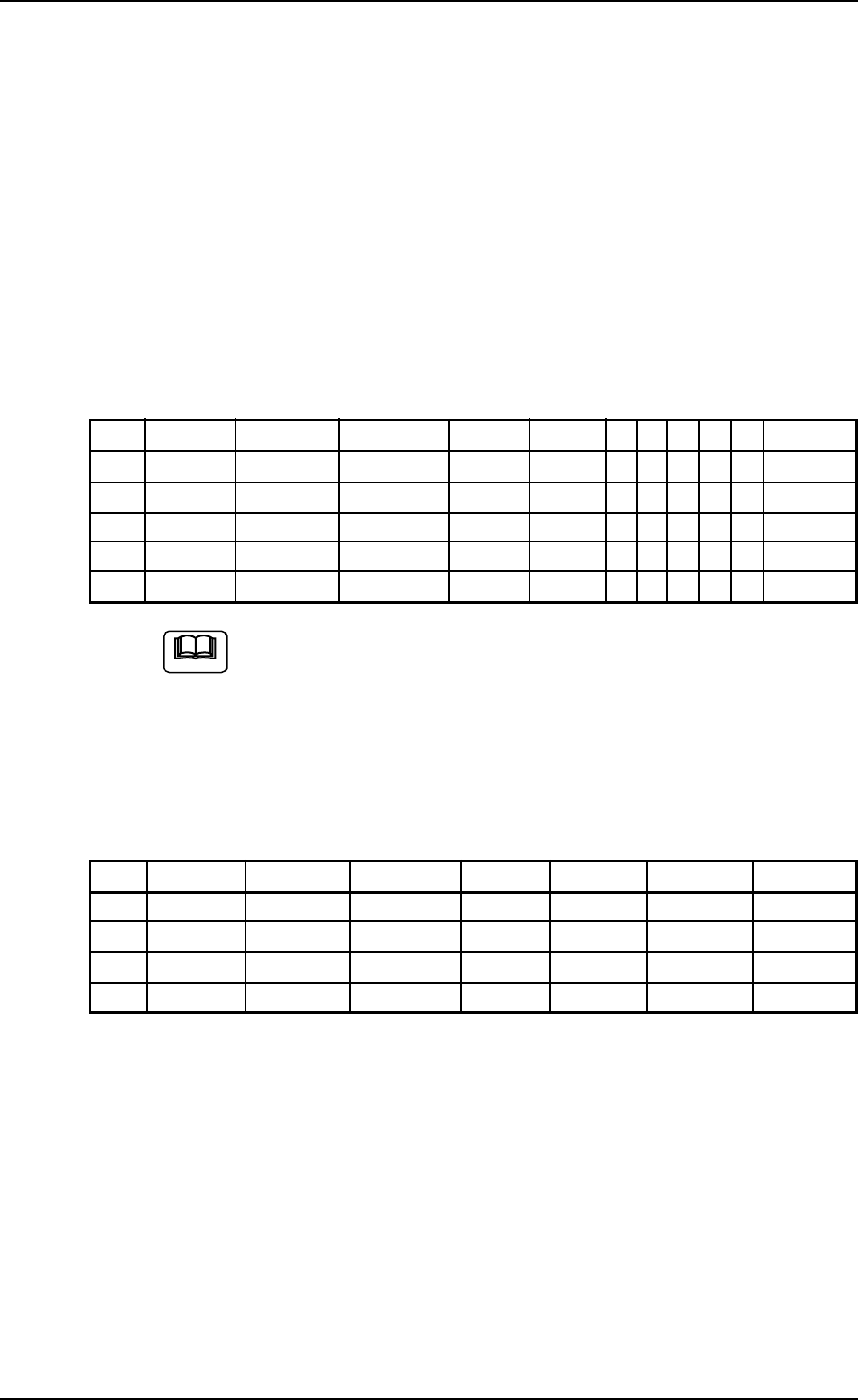
• Placement Data (P-data)
Table 6
P-No. X [mm] Y [mm] Z H [mm] Fdr. No. C S HD PU V Comment
1 BX
1
BY
1
000°00′ +0.00 000 B - 0 0 00
2 X
1
Y
1
000°00′ +0.00 101 - - 2 0 00
3 X
2
Y
2
090°00′ +0.00 115 - - 1 0 00
4 X
3
Y
3
180°00′ +0.00 105 - - 2 0 00
5 000.00 000.00 000°00′ +0.00 000 P - 0 0 00
(a) Set the coordinates (BX
1
, BY
1
) of the bad mark in the "X
[mm]" and "Y [mm]" text boxes and "B" (control com-
mand) in the "C" text box of the "P-No. 1" step.
(b) Set "P" or "Q" as a control command in the last line (last
step No.).
(5) Creation of Placement Data (O-data) U01
Table 7
O-No. X [mm] Y [mm] Z H C Comment B-X [mm] B-Y [mm]
1 OX
1
OY
1
000°00′ +0.00 - 000.00 000.00
2 OX
2
OY
2
000°00′ +0.00 - 000.00 000.00
3 OX
3
OY
3
000°00′ +0.00 - 000.00 000.00
4 000.00 000.00 000°00′ +0.00 E 000.00 000.00