SOM-1653-001.pdf - 第25页
Tg0756-PM-SO 0206-001 24 5.5 Sensitivity Setting of Bad Mark Sensor (3) Set the product P .C.B. on the P .C.B. positioning section. (4) Set the parameters at the operation window . Press the [Unit Adjustment] button on t…

Tg0756-PM-SO0206-001 23
5.4 Program Change
5.4 Program Change
Change to the current pattern program (the program for current pro-
duction) and perform the setup operation.
Refer to the main machine instruction manual for details.
5.5 Sensitivity Setting of Bad Mark Sensor
When the unit P.C.B. B.B.R. detection function is used, be sure to ad-
just the amplifier sensitivity of the sensor.
Procedure for Amplifier Sensitivity Adjustment
(1) Change to the current pattern program (the program for current pro-
duction) and perform the setup operation.
(2) Put a bad mark on the P.C.B. to be produced.
To put a black mark
Put a bad mark on the specified position of the second unit P.C.B.
Note: Do not put any bad mark on the first unit P.C.B.
To put a white mark
Put a bad mark on the specified position of the first unit P.C.B.
Note: Do not put any bad mark on the second unit P.C.B.
(a) Use a black mark for a comparatively bright P.C.B. (P.C.B.
with a lot of light reflex).
Use a white mark for a comparatively dark P.C.B. (P.C.B.
with a little light reflex).
(b) When the selection is changed (from "Black Mark" to "White
Mark" or vice versa), be sure to change the mark image
("Black (E/NR)" or "White (E/R)") in the "Image" text box
of the pattern program data.
Note
Tg0756-PM-SO0206-001 24
5.5 Sensitivity Setting of Bad Mark Sensor
(3) Set the product P.C.B. on the P.C.B. positioning section.
(4) Set the parameters at the operation window.
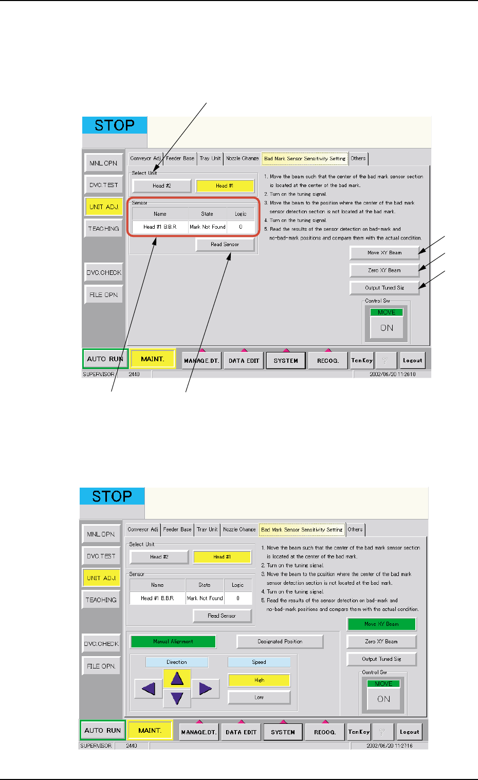
Press the [Unit Adjustment] button on the "Maintenance" sub-menu
bar and then press the [Bad Mark Sensor Sensitivity Setting] tab.
Fig. 24
(5) Select the [Head #1] button in the *1 "Select Unit".
(6) Press the *2 [Move XY Beam] button.
Fig. 25 Manual Alignment
*2
*6
*3
*5 *4
*1

Tg0756-PM-SO0206-001 25
5.5 Sensitivity Setting of Bad Mark Sensor
Fig. 26 Designated Position
(7) Use the "Manual Alignment" or "Designated Position" function to
move the beam so that the center of bad mark sensor detection
section is aligned with the center of bad mark.
(8) Press the [ENABLE] button on the operation panel within 2 sec-
onds after pressing the *3 [Output Tuned Sig] button and "Move"
[ON] button.
(9) Use the "Manual Alignment" or "Designated Position" function and
move the beam to a position where the center of the bad mark
sensor detection section is not located on the bad mark.
(10) Press the [ENABLE] button on the operation panel within 2 sec-
onds after pressing the *3 [Output Tuned Sig] button and "Move"
[ON] button.
(11) Check the sensor detecting condition.
Move the beam to a position where the center of the bad mark
sensor detection section is aligned with the center of bad mark and
press the *4 [Read Sensor] button.
Check the data in the *5 "Sensor" data boxes to see that it is reflect-
ing the P.C.B. actual conditions.
Move the beam to the position where the center of the bad mark
sensor detection section is not located on the bad mark and press
the *4 [Read Sensor] button.
Check the data in the *5 "Sensor" data boxes to see that it is reflect-
ing the P.C.B. actual conditions.
(12) Select the [Head #2] button in *1 "Select Unit" and repeat the steps
(6) through (11).
(a) When the *6 [Zero XY Beam] button is pressed, the XY
beam is returned to origin.
(b) Calculation method for the value to be put in "Position"
data box.
• Bad Mark Position for Overall P.C.B. B.B.R.
X = P.C.B. Origin Offset X (horizontal)
+ Overall P.C.B. B.B.R. X (horizontal)
Y = P.C.B. Origin Offset Y (vertical)
+ Overall P.C.B. B.B.R. Y (vertical)
The standard bad mark or optional position bad mark is
set in Multi-unit P.C.B. B.B.R. mode.
Note