SOM-1653-001.pdf - 第27页
Tg0756-PM-SO 5.5 Sensitivity Setting of Bad Mark Sensor 0206-001 26 • Standard Bad Mark Position X = Offset X for Placement Data (P) + X for P-No. 1 + P .C.B. Origin Offset X (horizontal) + X for each O-No. step Y = Offs…

Tg0756-PM-SO0206-001 25
5.5 Sensitivity Setting of Bad Mark Sensor
Fig. 26 Designated Position
(7) Use the "Manual Alignment" or "Designated Position" function to
move the beam so that the center of bad mark sensor detection
section is aligned with the center of bad mark.
(8) Press the [ENABLE] button on the operation panel within 2 sec-
onds after pressing the *3 [Output Tuned Sig] button and "Move"
[ON] button.
(9) Use the "Manual Alignment" or "Designated Position" function and
move the beam to a position where the center of the bad mark
sensor detection section is not located on the bad mark.
(10) Press the [ENABLE] button on the operation panel within 2 sec-
onds after pressing the *3 [Output Tuned Sig] button and "Move"
[ON] button.
(11) Check the sensor detecting condition.
Move the beam to a position where the center of the bad mark
sensor detection section is aligned with the center of bad mark and
press the *4 [Read Sensor] button.
Check the data in the *5 "Sensor" data boxes to see that it is reflect-
ing the P.C.B. actual conditions.
Move the beam to the position where the center of the bad mark
sensor detection section is not located on the bad mark and press
the *4 [Read Sensor] button.
Check the data in the *5 "Sensor" data boxes to see that it is reflect-
ing the P.C.B. actual conditions.
(12) Select the [Head #2] button in *1 "Select Unit" and repeat the steps
(6) through (11).
(a) When the *6 [Zero XY Beam] button is pressed, the XY
beam is returned to origin.
(b) Calculation method for the value to be put in "Position"
data box.
• Bad Mark Position for Overall P.C.B. B.B.R.
X = P.C.B. Origin Offset X (horizontal)
+ Overall P.C.B. B.B.R. X (horizontal)
Y = P.C.B. Origin Offset Y (vertical)
+ Overall P.C.B. B.B.R. Y (vertical)
The standard bad mark or optional position bad mark is
set in Multi-unit P.C.B. B.B.R. mode.
Note
Tg0756-PM-SO
5.5 Sensitivity Setting of Bad Mark Sensor
0206-001 26
• Standard Bad Mark Position
X = Offset X for Placement Data (P) + X for P-No. 1
+ P.C.B. Origin Offset X (horizontal)
+ X for each O-No. step
Y = Offset Y for Placement Data (P) + Y for P-No. 1
+ P.C.B. Origin Offset Y (vertical)
+ Y for each O-No. step
• Optional Bad Mark Position
X = P.C.B. Origin Offset X (horizontal)
+ B-X for each O-No. step
Y = P.C.B. Origin Offset Y (vertical)
+ B-Y for each O-No. step
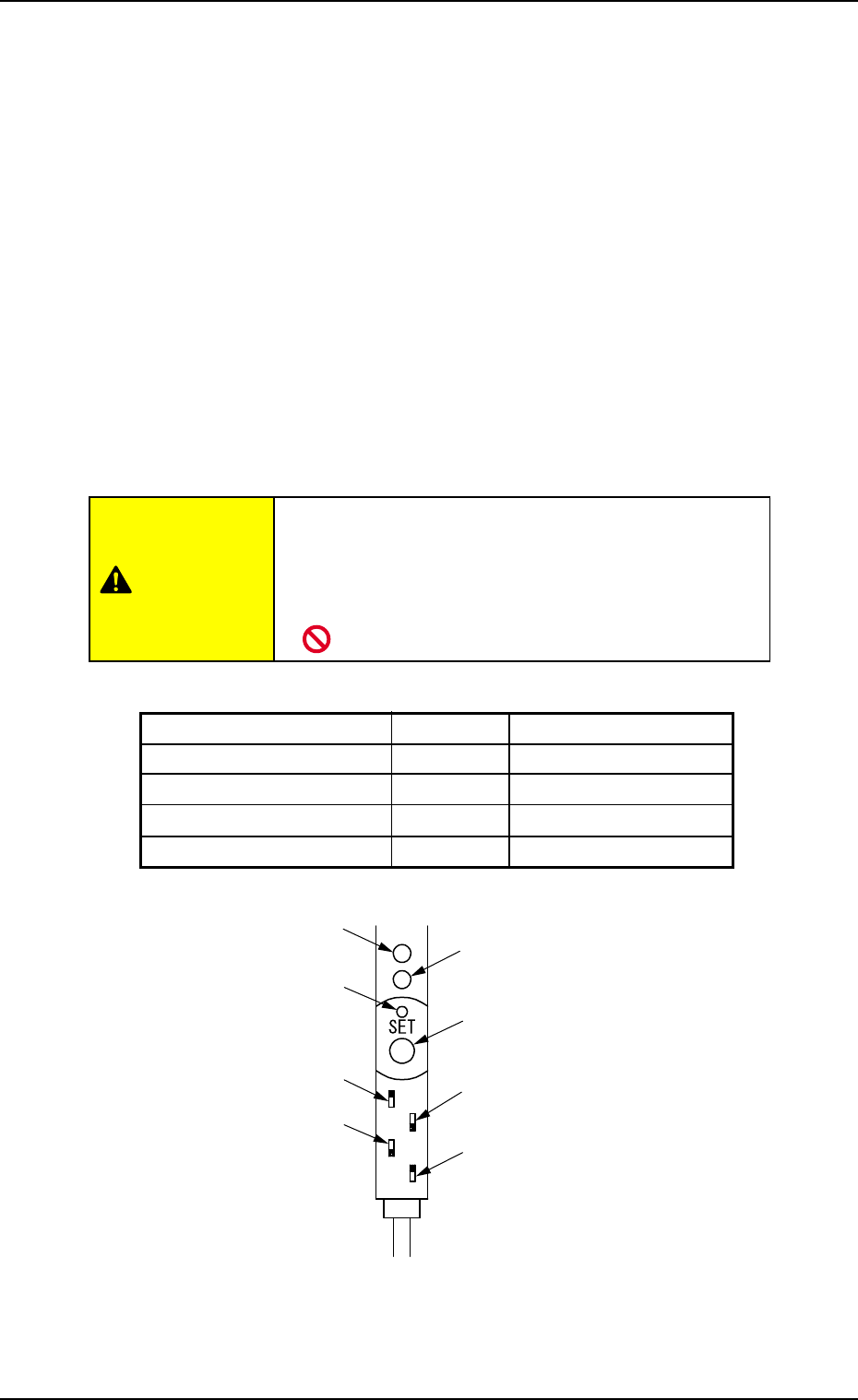
(c) Bad Mark Sensor Amplifier Setting
• Do not change the setting for the bad mark sen-
sor amplifier.
If the setting is changed, sensitivity cannot be set at
operation window.
CAUTION
Table 8
Switch Name Setting Dip Switch Position
Key Protection LOCK Upper
Output Timer Change OFF Lower Limit
Output Change L. ON Lower
FINE/TURBO Change FINE Upper
Fig. 27 Bad Mark Sensor Amplifier (-N701)
Stable Operation Indicator Lamp
(Green LED)
SET Button
Output Timer Switch
FINE/TURBO Switch
Operation Indicator Lamp
(Red LED)
Tuning Indicator Lamp
(Yellow LED)
Key Protect Switch
Output Switch

Tg0756-PM-SO0206-001 27
5.6 Pattern program filling in sheet
5.6 Pattern program filling in sheet
Pattern Program Name Date of Preparation
Comment 1 Prepared by
Comment 2
(1) Operation Data
P.C.B. Data
Unit P.C.B. B.B.R. Mode Disable/Standard/Optional
/Standard (Camera)/Optional (Camera)
Image Black (E/NR), White (E/R)
Component prechuck Disable/Enable
Sequence Bad Mark/Recognition
Detection head Head #1/Head #2
Overall P.C.B. B.B.R. Disable/Enable
X [mm] (Horizontal) . mm
Y [mm] (Vertical) . mm
(2) Placement Data (O) U###
O-No. B-X [mm] B-Y [mm]
1. .
2. .
3. .
4. .
5. .
6. .
7. .
8. .
9. .
0. .
1. .
2. .
3. .
4. .
5. .
6. .
7. .
8. .
9. .
0. .