SOM-1653-001.pdf - 第20页
Tg0756-PM-SO 0206-001 19 5.2 Example of Pattern Program Creation Note (4) Creation of Placement Data (P-data) U01 • Unit Control Set the same parameters as in "V olume 3: Programming and Ma- chine Data, Section 2, 3…
Tg0756-PM-SO0206-001 18
5.2 Example of Pattern Program Creation
(2) Creation of Operation Data
• P.C.B. Data
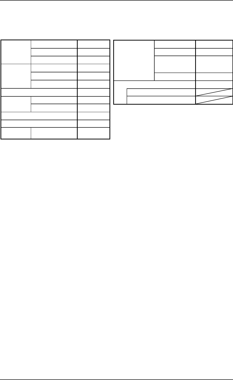
Table 5
Placement mode
P.C.B. positioning reference
P.C.B.
locate
Unit P.C.B. B.B.R.
Mode Standard
Mark Image Dark (E/NR)
Component
prechuck
Disable
Sequence Bad Mark
Overall P.C.B. B.B.R. Disable
X (Horizontal)
Y (Vertical)
P.C.B. size
P.C.B.
origin offset
X (Horizontal)
Y (Vertical)
T (Thickness)
X (Horizontal)
Y (Vertical)
Z=Theta
P.C.B. height offset
Pre-Placed
cmpnt
thikness
335.00 [mm]
255.00 [mm]
1.6 [mm]
+00.000 [mm]
+00.000 [mm]
+00°000′
+00.000 [mm]
0.00 [mm]
0.00 [mm]
Placement
Rear Left
Outline
P.C.B. top
P.C.B. bottom
Datum
• P.E.C. Recognition Data
Set "Disable" in the "P.E.C. recognition function" text box.
Do not set any parameter in the other text boxes.
• P.E.C. Recognition Mark Data
Do not create this data.
• Setup Data
Create this data when the automatic setup function should be used.
(3) Creation of Placement Feeder Location Data
Set the same parameters as in "Volume 3: Programming and Ma-
chine Data, Section 2, 3.1 Single Pattern" in the instruction manual
for the main machine.
Tg0756-PM-SO0206-001 19
5.2 Example of Pattern Program Creation
Note
(4) Creation of Placement Data (P-data) U01
• Unit Control
Set the same parameters as in "Volume 3: Programming and Ma-
chine Data, Section 2, 3.1 Single Pattern" in the instruction manual
for the main machine.
• Unit P.C.B. B.B.R.
Set "Disable" in this text box.
Do not set any parameter in the other text boxes.
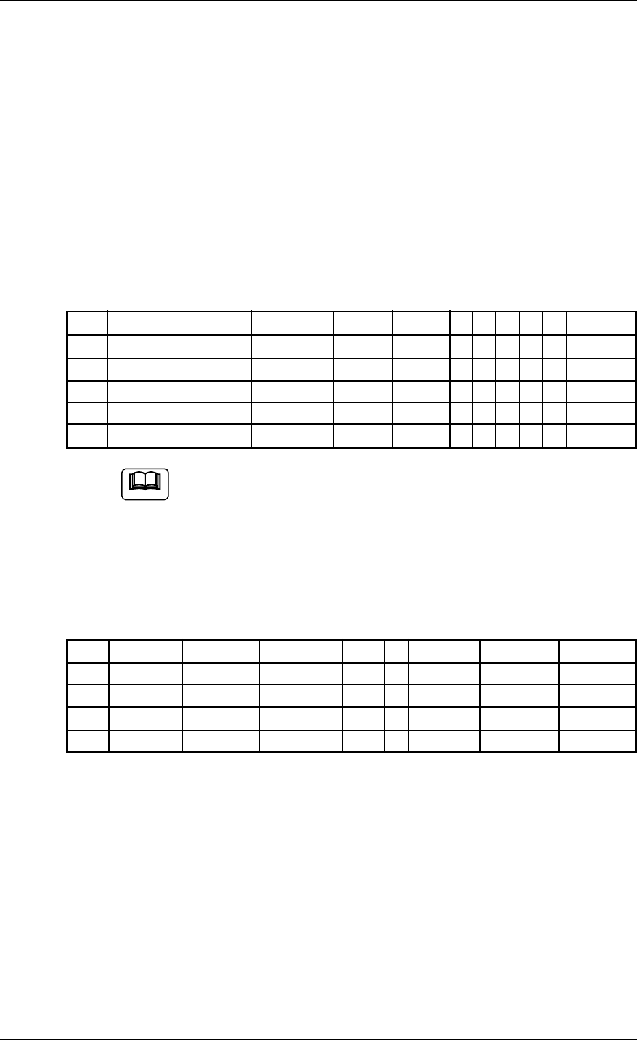
• Placement Data (P-data)
Table 6
P-No. X [mm] Y [mm] Z H [mm] Fdr. No. C S HD PU V Comment
1 BX
1
BY
1
000°00′ +0.00 000 B - 0 0 00
2 X
1
Y
1
000°00′ +0.00 101 - - 2 0 00
3 X
2
Y
2
090°00′ +0.00 115 - - 1 0 00
4 X
3
Y
3
180°00′ +0.00 105 - - 2 0 00
5 000.00 000.00 000°00′ +0.00 000 P - 0 0 00
(a) Set the coordinates (BX
1
, BY
1
) of the bad mark in the "X
[mm]" and "Y [mm]" text boxes and "B" (control com-
mand) in the "C" text box of the "P-No. 1" step.
(b) Set "P" or "Q" as a control command in the last line (last
step No.).
(5) Creation of Placement Data (O-data) U01
Table 7
O-No. X [mm] Y [mm] Z H C Comment B-X [mm] B-Y [mm]
1 OX
1
OY
1
000°00′ +0.00 - 000.00 000.00
2 OX
2
OY
2
000°00′ +0.00 - 000.00 000.00
3 OX
3
OY
3
000°00′ +0.00 - 000.00 000.00
4 000.00 000.00 000°00′ +0.00 E 000.00 000.00
Tg0756-PM-SO0206-001 20
5.3 "Pattern Program" Edit Window
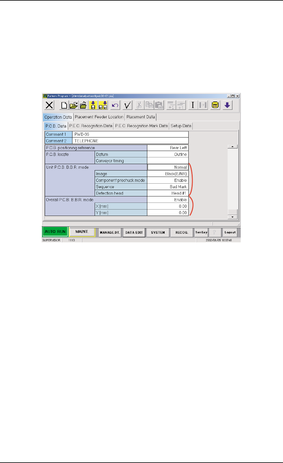
5.3 "Pattern Program" Edit Window
5.3.1 "P.C.B. Data" Tab
• Sheet Layout
When the "P.C.B. Data" tab is pressed in the "Operation Data" tab
sheet, the following tab sheet appears.
*1
*2
Fig. 22 "P.C.B. Data" Tab Sheet
• Sheet Composition
Each parameter is displayed or can be entered.
*1 Unit P.C.B. B.B.R.
Mode
Image, Component prechuck mode, Sequence
When a parameter other than "Disable" is selected for "Mode",
it is required to enter parameters in the text boxes.
*2 Overall P.C.B. B.B.R.
X [mm] (Horizontal), Y [mm] (Vertical)
When "Enable" is selected for "Overall P.C.B. B.B.R.", it is re-
quired to enter parameters in the text boxes.