s26030829.pdf - 第13页
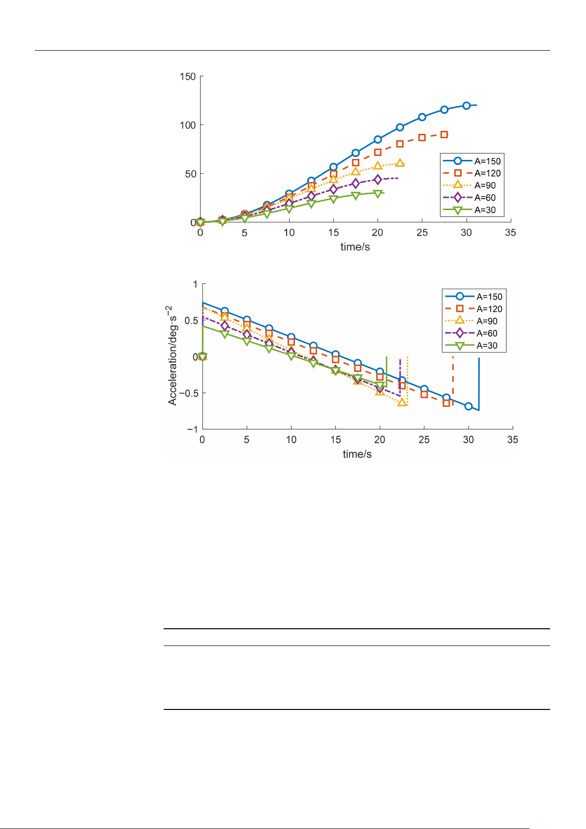
Sensors 2026 , 26 , 829 13 of 21 Displacement/deg Figure 9. Displacement-time profiles for dif ferent planned displacements. Figure 10. Acceleration-time profiles for dif ferent planned displacements. As indicated in T abl…
Sensors 2026, 26, 829
12 of 21
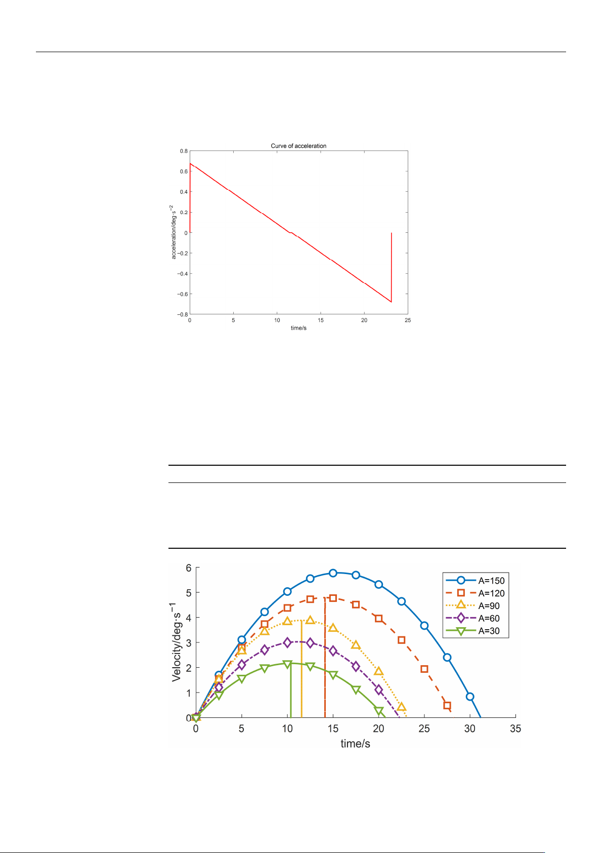
parameters is shown in Figure 5. Overall, the profile is relatively smooth, with no abrupt
changes in velocity. Moreover, as indicated by the displacement curve in Figure 6 and
the acceleration curve in Figure 7, the angular variation is gradual, and the acceleration
exhibits no pronounced fluctuations.
Figure 7. Acceleration–time profile.
5. Comparison Under Different Initial Input Conditions
(1) By modifying the motion range of the wafer-transfer manipulator, i.e., varying the
angular displacement A, the corresponding trajectories and the residual vibration energy
can be rapidly fitted through iterative computation. With all other conditions unchanged,
the experimental results are summarized in Table 5 and Figures 8–10.
Table 5. Variation in Objective Function Values of Wafer Transfer Robot Arm at Different Displacements.
Displacement Runtime Vibration Energy Index E
vib
150 16.8 347.8261
120 13.8 347.8261
90 9.633 339.394
60 7.083 166.957
30 6.033 164.882
Figure 8. Velocity-time profiles for different planned displacements.
https://doi.org/10.3390/s26030829
Sensors 2026, 26, 829
13 of 21
Displacement/deg
Figure 9. Displacement-time profiles for different planned displacements.
Figure 10. Acceleration-time profiles for different planned displacements.
As indicated in Table 5, the residual vibration energy is strongly influenced by the total
angular displacement. When the angular change increases from 60
◦
to 90
◦
, the residual
vibration energy rises by 103.28%. Therefore, constraining the forearm angular variation to
within 60
◦
can significantly suppress vibrations induced by the flexible joint.
(2) To investigate the influence of the start-up acceleration on the motion performance
and vibration characteristics of the wafer-transfer manipulator, comparative experiments
were conducted by varying the start-up acceleration a while keeping the other control
parameters constant. The results are listed in Table 6 and Figures 11–13.
Table 6. Variation in Objective Function Values of Wafer Transfer Robot Arm at Different Startup Acceleration.
Startup Acceleration Runtime Vibration Energy Index E
vib
−5 12.6952 32.8125
10 13.9619 131.2500
20 8.2476 525.0000
40 5.6347 2149.8891
80 2.0144 9029.1039
https://doi.org/10.3390/s26030829
Sensors 2026, 26, 829
14 of 21
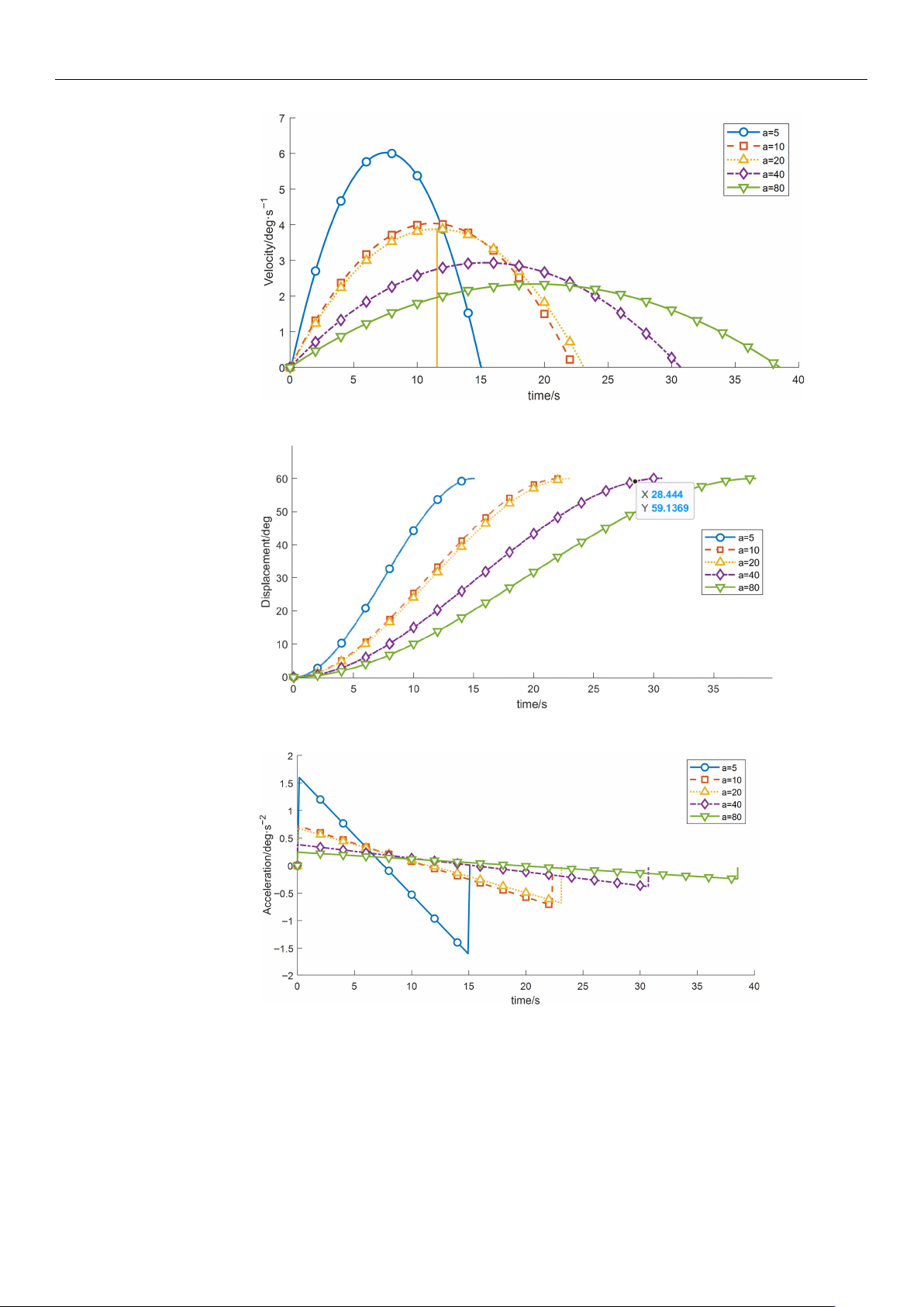
Figure 11. Velocity-time profiles for different start acceleration.
Figure 12. Displacement–time profiles for different start acceleration.
Figure 13. Acceleration–time profiles for different start acceleration.
As shown in Table 6, as a increases from 5 to 80, the overall operation time exhibits
a decreasing trend, whereas the vibration energy index increases rapidly in a nonlinear
manner. These results demonstrate that a larger start-up acceleration is beneficial for
reducing the operation time and improving transfer efficiency. However, excessive start-up
acceleration introduces stronger impact loads and excites high-frequency modes of the
manipulator, leading to a substantial increase in vibration. Hence, a typical trade-off exists
between efficiency and vibration suppression. Considering both efficiency and stability,
https://doi.org/10.3390/s26030829