s26030829.pdf - 第3页
Sensors 2026 , 26 , 829 3 of 21 the influence of random disturbances [ 15 – 17 ]. Researchers have proposed various new optimization algorithms and intr oduced differ ent solution strategies to address the short- comings …

Sensors 2026, 26, 829
2 of 21
The vibration suppression methods for robotic arms can be categorized into passive
and active vibration suppression. Passive vibration suppression primarily involves op-
timizing the topology to improve mass distribution, using lightweight, stiff materials to
enhance the equivalent stiffness, and incorporating damping devices and energy-absorbing
components to suppress vibrations through physical mechanisms. These passive vibration
suppression schemes do not require external energy input, are cost-effective, but have
limited adaptability to time-varying operating conditions, making them difficult to meet
the requirements of wafer transport robotic arms [
6
]. Active vibration suppression, on the
other hand, reduces the vibrations of the robot by improving control strategies, thereby en-
hancing motion precision and stability. PID control, with its simple and intuitive structure
and low implementation difficulty, is widely used in the motion control of industrial robots
to suppress elastic vibrations in robotic arms. Yang C et al. employed PID fuzzy control to
suppress elastic vibrations in flexible robotic arms, improving the positioning and control
accuracy of piezoelectric flexible arm ends [
7
]. Guo et al. proposed a tracking control sys-
tem integrating an incremental PID controller and a sliding mode robust controller, which
demonstrated stronger accuracy, stability, and anti-interference capabilities compared to
traditional PID control [
8
]. In addressing similar robotic arm control problems, Wazzan
utilized PID sliding mode control combined with a genetic algorithm to tune controller
parameters, effectively improving the performance of the robotic arm’s PID controller [
9
].
Despite the simplicity and intuitiveness of these control methods, these controllers are
often optimized based on specific models, and their control parameters are difficult to meet
the requirements for high precision and stability, especially when dealing with complex
robotic arm structures or variable working environments.
Recently, researchers have commonly employed vibration suppression trajectory op-
timization to address the limitations of both passive and active vibration suppression,
providing a more cost-effective and universally applicable solution for robotic arm vibra-
tion control. This approach has become one of the key research focuses in the field of
robotic arm control [
10
]. These methods formulate trajectory planning as a multi-objective
or constrained optimization problem by simultaneously considering system dynamics,
motion time, energy consumption, joint smoothness, and end-effector vibration, and they
commonly introduce metaheuristic optimization algorithms to search for optimal solutions.
These optimization algorithms, inspired by natural phenomena and biological behaviors,
offer new approaches for solving trajectory planning and constrained optimization prob-
lems of this nature [
11
]. The development of metaheuristic optimization algorithms can be
broadly divided into two directions: global search and local optimization. Among them,
the Genetic Algorithm (GA) is widely used in various global search optimization problems
due to its strong capability in handling complex constraints, combinatorial optimization,
and global exploration. Xu Qiang et al. proposed a genetic algorithm combined with
a simulated annealing mechanism, which further improved the optimization accuracy,
shortened the robotic arm’s motion time, and enhanced its work efficiency [
12
]. Meanwhile,
Kheshti et al. applied genetic algorithms to adjust the gain optimization of sliding mode
controllers, reducing the time required for a manipulator arm to complete a predefined mo-
tion trajectory [
13
]. However, the computational model of genetic algorithms is relatively
complex, and its use has certain limitations. In contrast, Particle Swarm Optimization (PSO)
has a simpler algorithm structure and stronger local optimization capability. In this context,
Wu N et al. proposed an improved particle swarm optimization algorithm (RTPPSO) to
optimize the robotic arm’s joint angles or path. By introducing an adaptive weight strategy,
they significantly improved the robotic arm’s work efficiency [
14
]. However, when solving
complex problems with multiple dimensions, strong constraints, and strong coupling,
PSO is prone to accuracy degradation and insufficient global search capability due to
https://doi.org/10.3390/s26030829

Sensors 2026, 26, 829
3 of 21
the influence of random disturbances [
15
–
17
]. Researchers have proposed various new
optimization algorithms and introduced different solution strategies to address the short-
comings of these two algorithms. Yue et al. applied a gray wolf optimization algorithm with
a probabilistic disturbance strategy to solve the time-optimal problem. This optimization
strategy effectively balanced the weight between local optimization and global search [
18
].
However, the gray wolf population may converge around suboptimal individuals, leading
to premature convergence issues [
19
,
20
]. Pu Q et al. introduced an improved wild dog
optimization algorithm for robotic arm time-impact optimization [
21
,
22
], but they did not
perform tests for solving high-dimensional problems using the wild dog optimization
algorithm. Additionally, to improve global search capability and address the issue of search
direction disturbance, Lv Yun peng et al. proposed an inverse kinematics solver based on
a multi-strategy improved dung beetle optimization algorithm. However, this improved
algorithm has not been applied to the multi-objective vibration optimization direction [
23
].
Widyianto Agus et al. addressed the issue of the shipboard two-degree-of-freedom robotic
arm being affected by environmental factors and proposed a real-time tuning of PD con-
trol parameters based on an ant colony algorithm, significantly improving the stability of
shipboard equipment [
24
]. Abro et al. combined ant colony optimization’s pheromone
learning with the Denavit–Hartenberg (DH) method to develop a robotic arm error model,
further enhancing the accuracy of global search and improving the reliability and accuracy
of industrial robotic systems [
25
]. However, the ant colony algorithm is heavily depen-
dent on the initial model, making it difficult to avoid local optimal solutions. The Whale
Optimization Algorithm (WOA) introduced a random spiral search step, eliminating the
need for crossover and mutation operators, with a simpler program structure. Wang Fang
et al. applied a hybrid whale optimization algorithm to optimize the time-impact optimal
trajectory of industrial robotic arms, using fifth-order B-splines for interpolation planning
of motion trajectories in joint space [
26
]. However, the performance of this algorithm signif-
icantly deteriorates in a multi-constraint environment and requires further integration with
various improvement strategies [
27
]. The Graylag Goose Optimization (GGO) algorithm
introduced a group migration strategy [
28
], demonstrating strong search capabilities in
multi-objective problems and efficient local optimization when facing suboptimal solu-
tions. Ashish Sharma et al. conducted eight multi-objective benchmark tests, with the
results showing that the Multi-Objective Graylag Goose Optimization (MOGGO) algorithm
exhibited excellent performance in terms of convergence [29].
In summary, this paper introduces the GGO algorithm into the vibration suppression
trajectory optimization problem of wafer transport robotic arms, providing a new feasible
solution for multi-objective trajectory optimization. This study constructs the end dynamics
equation of the flexible lower arm and integrates a multi-objective optimization model
involving motion time, energy, and impact. Based on the multi-objective GGO algorithm,
the trajectory parameters are solved, aiming to generate a set of Pareto-optimal trajectories
with superior overall performance, offering a novel and efficient solution to improve the
performance of the wafer transport system.
2. Establishment of the Dynamics Model for Wafer Transport
Robotic Arm
In this study, the wafer transport robotic arm mainly consists of two links [
30
,
31
]. The
upper (first) link is rigidly connected to the motor, while the lower (second) link is driven
by another motor via a flexible steel belt inside the upper link, which can be regarded as a
flexible motion joint. During motion, only the bending stress of the steel belt is considered.
The end-effector is coupled to the posture of the upper link through the steel belt embedded
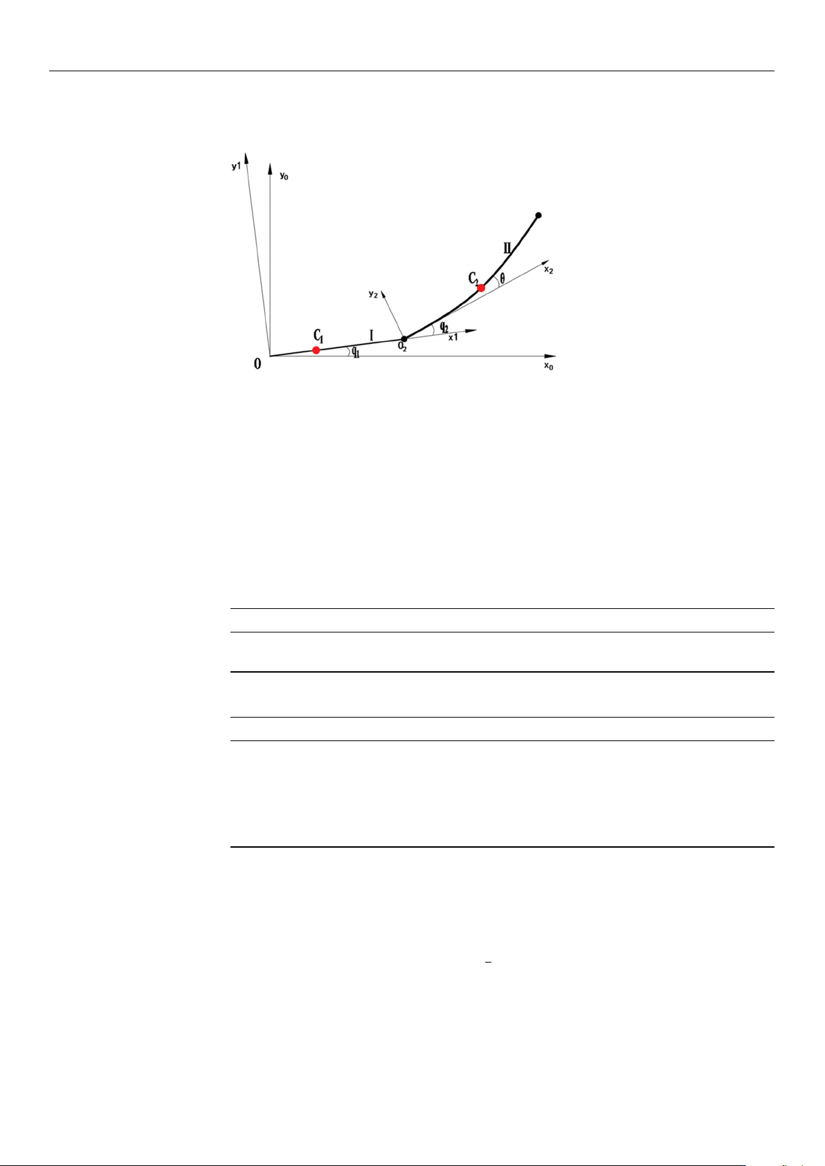
inside the lower link. As shown in Figure 1, q1 and q2 denote the rotational joint angles
https://doi.org/10.3390/s26030829
Sensors 2026, 26, 829
4 of 21
defined by the DH parameters, whereas
θ
represents the elastic deformation angle of the
flexible transmission element.
Figure 1. Motion Model of Wafer Transport Robotic Arm.
Table 1 shows the simplified model of the wafer transport robot, which consists of the
rigid link I (upper arm) and the flexible link II (lower arm). The world coordinate system
X
0
OY
0
is established with the base as the origin, the coordinate system X
1
OY
1
is set at the
end-point of link I (upper arm), and the coordinate system X
2
O
2
Y
2
is established at the
end-point of link II (lower arm). C
1
and C
2
represent the center of mass of the two links.
q
1
is the rotation angle of the primary arm, q
2
is the rotation angle of the secondary arm,
and
θ
is the deformation of the flexible lower arm. The structural parameters of the wafer
transfer robotic arm in this study are shown in Table 2.
Table 1. D-H Parameter Table of the Wafer Handling Robot Arm.
Arm/li q
i
/
◦
d
i
/mm l
i
/mm α
i
/
◦
L
1
0–120 0 240 0
L
2
0–120 0 240 0
Table 2. Parameters of Components of the Wafer Transport Robotic Arm.
Structure Value
Primary arm length/L
1
240 mm
Secondary arm length/L
2
240 mm
Mass of Primary arm/m
1
2.757 kg
Mass of secondary arm/m
2
2.165 kg
The center of gravity of the primary arm/Lc
1
0.4 L
1
The center of gravity of the secondary arm/Lc1 0.5 L
2
First, based on the Lagrange method, the dynamic equations of a planar two-degree-of-
freedom rigid robot are established. First, the robot’s potential energy equation is analyzed.
The robot’s forearm can be regarded as a flexible arm rod, and its elastic potential energy
can be expressed as
V
e
=
1
2
k(q
2
− θ
2
) (1)
Here, the
θ
refers to the ideal angle of the forearm when no deformation occurs. Since
the robot prototype moves parallel to the ground throughout, gravitational potential energy
is not taken into account. The kinetic energy expression includes both the rotational kinetic
energy of each link and the translational kinetic energy of the link centers of mass.
https://doi.org/10.3390/s26030829