s26030829.pdf - 第17页
Sensors 2026 , 26 , 829 17 of 21 output module is constructed to generate the r eference pr ofiles of the joint angle, angular velocity , and angular acceleration. Meanwhile, a random disturbance module is connected exter…
Sensors 2026, 26, 829
16 of 21
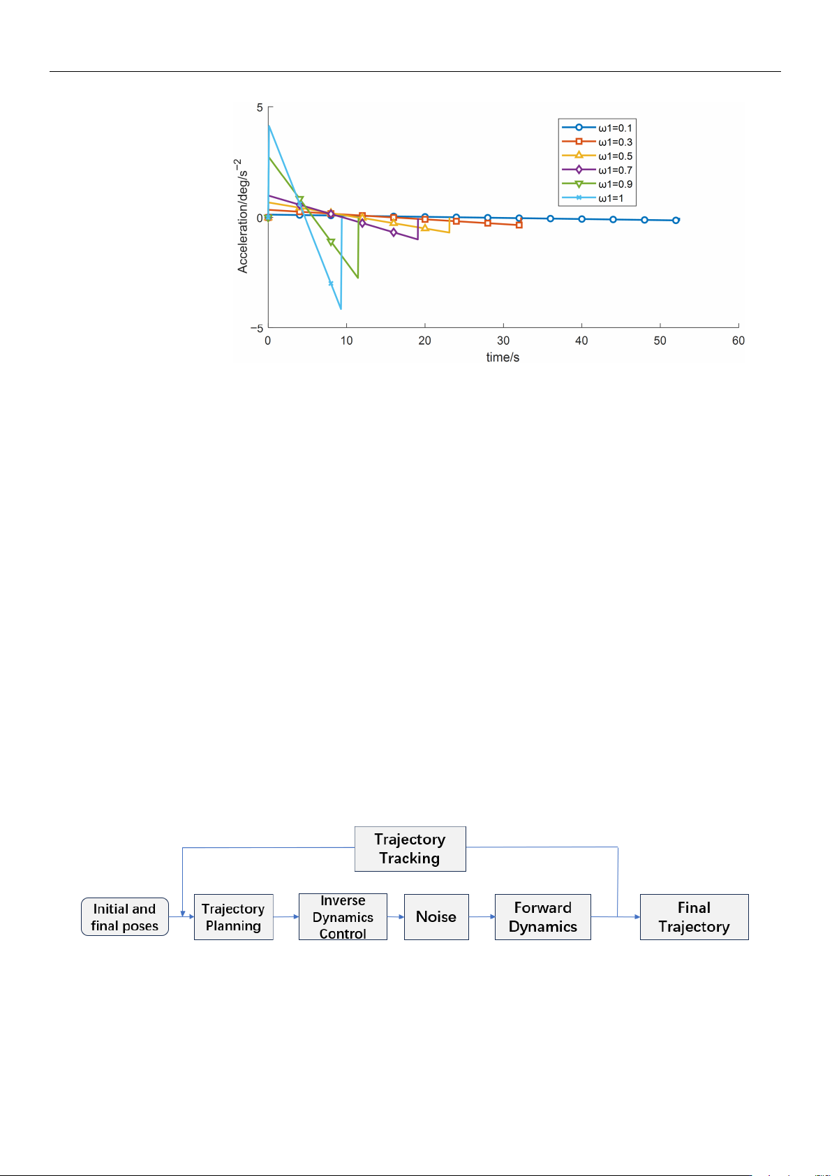
Figure 16. Acceleration–time profiles for different time weight.
Table 7 shows that the sensitivity of both the total operation time and the vibration
energy index to w1 is relatively low, and the current optimization results therefore lie in an
approximately flat Pareto region. Overall, although increasing the time weight reduces the
operation time, it may induce higher vibration energy, implying greater instability and/or
energy consumption.
6. Simulation Analysis Based on Simulink
In this study, a Simulink-based trajectory simulation platform was Established. The
optimal trajectory parameters obtained from the optimization algorithm were imported
into the platform to simulate and evaluate the manipulator’s stability under external
disturbances. The external disturbance shown in Figure 17 is modeled as a bounded random
torque applied to the joint actuator to emulate unmodeled dynamics and environmental
perturbations in wafer-handling operations. The disturbance is defined as:
τ
d
(t) = τ
max
ξ(t), ξ(t) ∈ [−0.1, 0.1] (20)
where
ξ
(t) is a zero-mean bounded random process and
τ
max
denotes the disturbance
bound. In the Simulink implementation,
ξ
(t) is generated using a random source (e.g., a
band-limited noise or uniform random sequence) and then constrained by saturation to
ensure |
τ
d
(t)|
≤ τ
max
. This bounded setting provides a physically meaningful robustness
test while avoiding unrealistically large excitation.
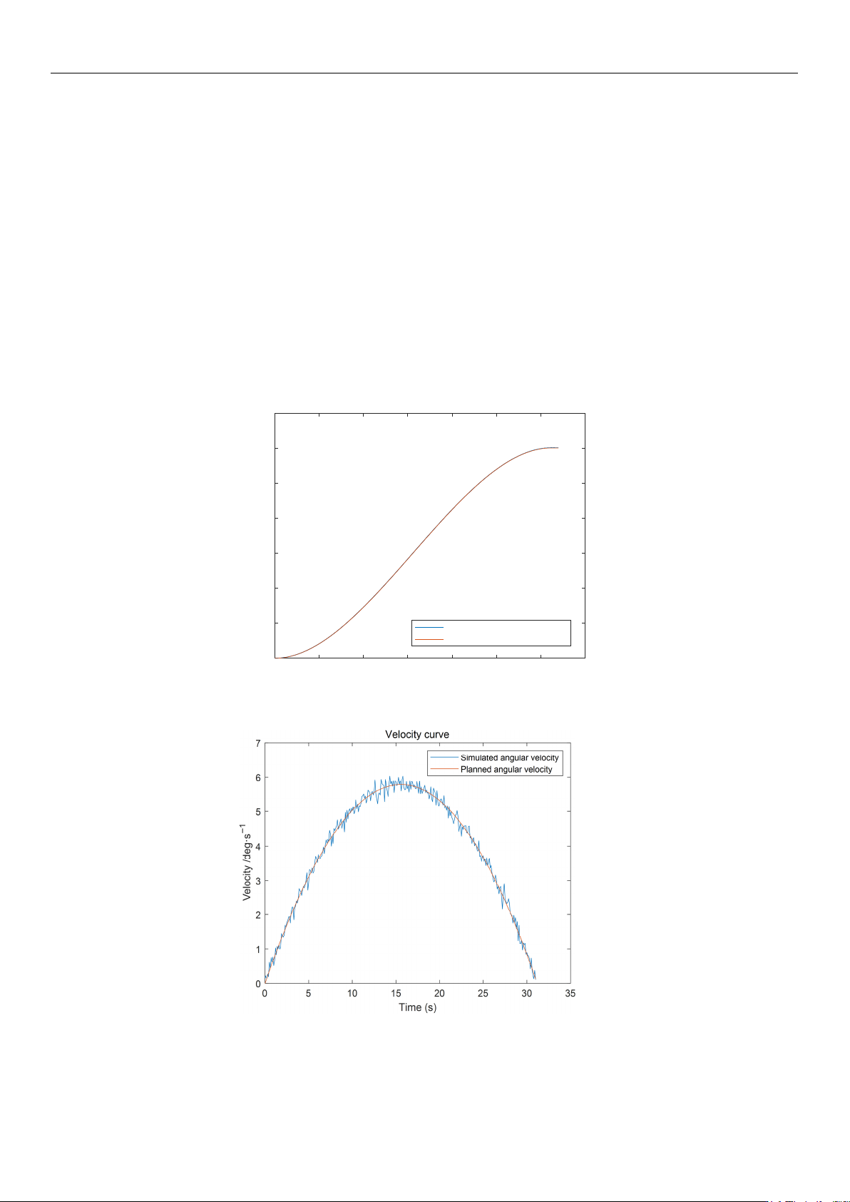
Figure 17. Robotic Arm Simulation System Flowchart.
This represents unmodeled dynamics and external perturbations typically encountered
in industrial wafer-handling environments.
To control the robot motion, the Simulink control program first initializes the system
by setting the manipulator coordinates to the prescribed initial state [
39
]. Based on the
planned trajectory parameters obtained from the preceding simulations, a smooth-function
https://doi.org/10.3390/s26030829
Sensors 2026, 26, 829
17 of 21
output module is constructed to generate the reference profiles of the joint angle, angular
velocity, and angular acceleration. Meanwhile, a random disturbance module is connected
externally to provide an excitation torque, which is applied as the external input torque
τ
to
the dynamic planning module. A closed-loop control function is then established according
to the governing dynamic equations. The output angular acceleration is integrated twice to
obtain the simulated angular velocity and angular displacement, and the resulting data
are exported to spreadsheets. Furthermore, inverse kinematics is employed to inversely
infer the effect of the external disturbance and back-calculate the corresponding driving
torque, thereby completing the closed-loop simulation test module [
40
]. In this study,
angular displacement, angular velocity, angular acceleration, and joint torque are adopted
as evaluation metrics to assess the time-planning performance and vibration-suppression
capability of the wafer-transfer robot using the Simulink test platform. The integrated
simulation platform is executed, and the Scope outputs are exported to the workspace via
the To Workspace function, yielding the simulation results shown in Figures 18–20.
0 5 10 15 20 25 30 35
Time (s)
0
20
40
60
80
100
120
140
Displacement/deg
displacement curv
e
Simulated angular displacement
Planned angular displacement
Figure 18. Robotic Arm Displacement Curve.
Figure 19. Robotic Arm Velocity Curve.
https://doi.org/10.3390/s26030829
Sensors 2026, 26, 829
18 of 21
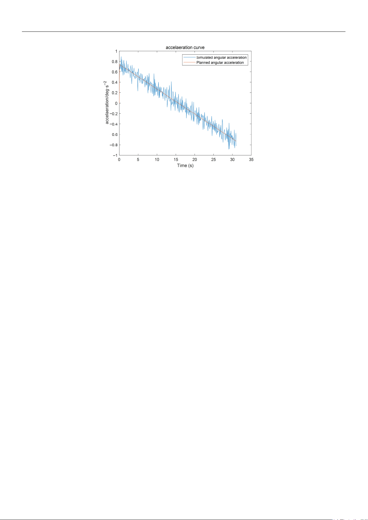
Figure 20. Robotic Arm Acceleration Curve.
As indicated by the simulation results in Figure 18, the planned joint angular displace-
ment profile of the forearm joint is in close agreement with the simulated tracking angular
displacement over the entire motion interval. The two curves almost overlap in the initial
stage, the acceleration and constant-velocity transition stage, and the final deceleration
stage, exhibiting an overall smooth S-shaped trajectory. In terms of tracking performance,
the tracking angular displacement shows no evident overshoot or oscillation throughout the
motion, and the steady-state error at the end is virtually negligible, demonstrating that the
system achieves favorable dynamic response characteristics and high steady-state accuracy.
As shown by the simulation results in Figure 19, the planned angular velocity of
the forearm joint agrees well with the simulated tracking angular velocity over the entire
motion interval, with only a negligible deviation observed in the vicinity of the peak
velocity. No evident overshoot or oscillation is observed, indicating that the controller can
accurately track the desired angular-velocity command and that the system exhibits high
velocity-tracking accuracy and stability. Such a smooth velocity profile is beneficial for
reducing vibration levels in the joint and links, and it also prevents inertial impacts induced
by abrupt acceleration/deceleration, which is crucial for maintaining posture stability and
operational safety during wafer handling.
Furthermore, the planned and tracked angular accelerations of the forearm joint
remain highly consistent throughout the motion, as shown in Figure 19. Only minor local
high-frequency fluctuations are present, and no abrupt spikes or severe reverse jumps
are detected. Therefore, the proposed planning method can fundamentally suppress
structural vibrations of the manipulator, thereby supporting the stable operation of the
wafer-transfer robot.
Based on the simulation results shown in Figures 18–20, the vibration suppression per-
formance of the proposed trajectory planning method is further validated. Compared with
conventional polynomial-based trajectory planning approaches, the planned joint angular
displacement, velocity, and acceleration profiles exhibit smooth transitions without evident
oscillations or abrupt fluctuations. In particular, the angular-displacement fluctuation is
constrained within 0.01 deg/s, quantitatively indicating effective disturbance rejection and
enhanced dynamic smoothness, thereby supporting the vibration-suppression effect of the
proposed jerk-minimization trajectory planning strategy.
Moreover, by introducing the proposed improved multi-objective Gray Goose Opti-
mization (MOGGO) algorithm, the solution quality of the dual-objective vibration suppres-
https://doi.org/10.3390/s26030829