ASM-X-Spec-SX12V2-EN-DMS.pdf - 第15页
15 Placement Heads SIPLACE SX1/SX2 Standard Functions / Options SIPLACE SpeedStar (C&P20) SIPLACE MultiStar (CPP) S tandard- functions High-resolution camera, vacuum sensor , force measurement, component sensor , int…
14
Placement Heads SIPLACE SX1/SX2
Overview
Head modularity
The SIPLACE placement
machines are distinguished
by maximum flexibility in the
production process. This
flexibility is in part due to the
head modularity of the place-
ment machines, which allows
different placement head
variants to be configured to
suit the production require-
ments.
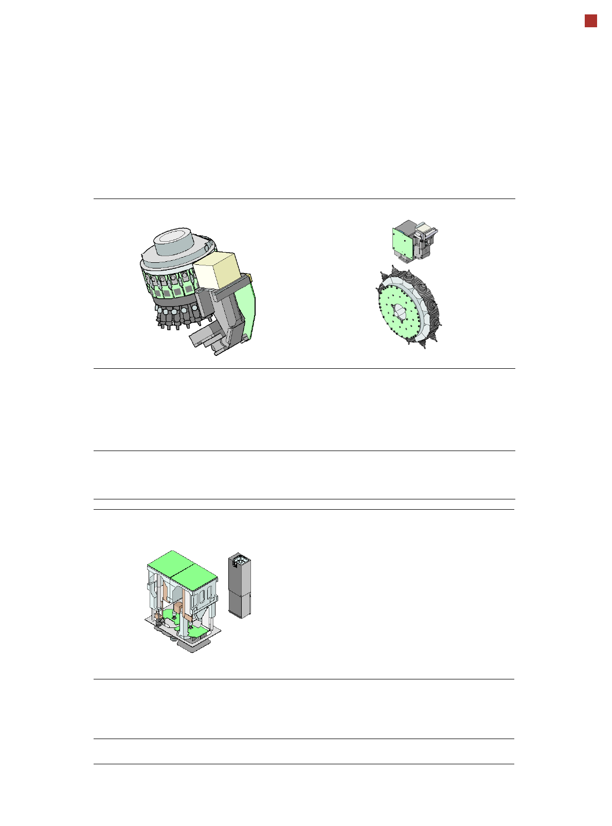
Collect&Place principle
The SIPLACE SpeedStar
operates according to the
Collect&Place principle i.e.
one cycle includes pickup or
"collection" of 20 compo-
nents, their optical centering
on the board and their rota-
tion into the required place-
ment angle and position.
They are then placed gently
and accurately onto the PCB.
This principle is particularly
suitable for high-speed
placement of standard
components.
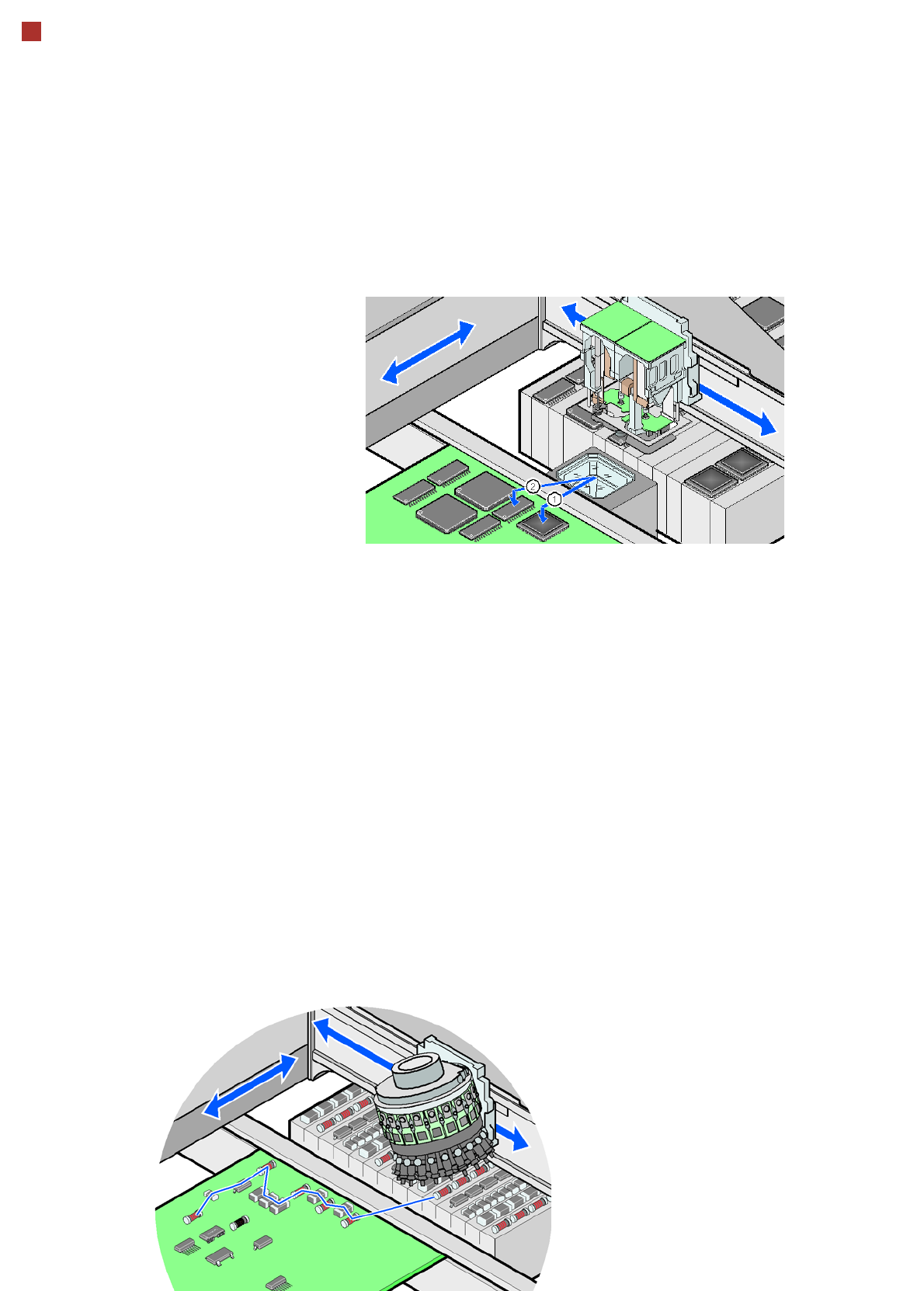
Pick&Place principle
The high-precision SIPLACE
TwinStar functions according
to the Pick&Place principle.
Two components are picked
up by the SIPLACE TwinStar
placement head, optically
centered on the way to the
placement position and then
rotated into the required
placement angle. This princi-
ple is ideally suitable for fast
and precise placement of
special components in the
fine pitch or super fine pitch
field, plus complex and
heavy components which
may need grippers.
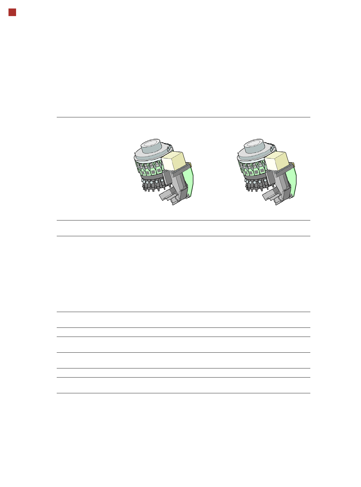
Mixed mode
The new SIPLACE MultiStar
uses both the Collect&Place
and the Pick&Place princi-
ple. Mixed Mode allows com-
bined use of these two
modes, which were previ-
ously separated from one
another, in one placement
cycle.
Control and self-learning
functions
The reliability of the
SIPLACE placement heads
can be enhanced even fur-
ther with various checking
and self-learning functions.
• Component sensor
Checks the presence of
the components on the
nozzle before the pickup
and placement process
• Digital camera
Checks the position of
each component on the
nozzle. This check is per-
formed in a single step,
with no extra time involved
but with optimum scan-
ning of each individual
component.
• Force sensor
Monitors the prescribed
component set-down
force.
The sensor stop proce-
dure enables compensa-
tion of height differences
during pickup and PCB
warpage during place-
ment.
• Vacuum sensor
Checks whether the com-
ponent was correctly
picked up or placed.
15
Placement Heads SIPLACE SX1/SX2
Standard Functions / Options
SIPLACE SpeedStar (C&P20) SIPLACE MultiStar (CPP)
Standard-
functions
High-resolution camera, vacuum
sensor, force measurement,
component sensor, integrated
turning station per segment,
PCB warpage check, individual
image of each component
Standard-
functions
High-resolution camera, vac-
uum sensor, force measure-
ment, component sensor,
integrated turning station per
segment, PCB warpage check,
individual image of each com-
ponent
Options Nozzle changer, special nozzles Options Nozzle changer, special noz-
zles, high-resolution head cam-
era for 01005 components,
stationary fine pitch camera
SIPLACE TwinStar (TH)
Standard-
functions
Stationary fine pitch camera,
vacuum sensor, force measure-
ment, nozzle changer, PCB war-
page check, individual image of
each component
Options Stationary flip chip camera, spe-
cial nozzles, grippers
16
Placement Heads SIPLACE SX1/SX2
SIPLACE SpeedStar (C&P20)
SIPLACE SpeedStar component
camera type 23 (C&P20)
SIPLACE SpeedStar component
camera type 41 (C&P20)
Component range
a
a) Please note that the placeable component range is also affected by the pad geometry, the customer-spe-
cific standards, the component packaging tolerances and the component tolerances.
01005 to 2220, Melf, SOT, SOD 01005 to 2220, Melf, SOT, SOD,
Bare-Die, Flip-Chip
Component spec.
max. height
min. lead pitch
min. lead width
min. ball pitch
min. ball diameter
min. dimensions
max. dimensions
max. weight
4 mm
0.25 mm
0.1 mm
0.4 mm
0.2 mm
0.4 mm x 0.2 mm
6 mm x 6 mm
1 g
4 mm
0.08 mm
0.03 mm
0.10 mm
0.05 mm
0.12 mm x 0.12 mm
6 mm x 6 mm
1 g
Programmable set-down
force
1.5 N - 4.5 N 1.5 N - 4.5 N
Nozzle types 10xx, 11xx, 12xx 10xx, 11xx, 12xx
X/Y accuracy
b
b) Accuracy values measured in accordance with vendor-neutral IPC standard.
± 41 µm/3
± 55 µm/4
± 41 µm/3
± 55 µm/4
Angular accuracy ± 0.5° / 3
± 0.7° / 4
± 0.5° / 3
± 0.7° / 4
Illumination levels 5 5
Possible illumination
level settings?
256
5
256
5