ASM-X-Spec-SX12V2-EN-DMS.pdf - 第23页
23 PCB conveyor SIPLACE SX1/SX2 Flexible dual conveyor Flexible dual conveyor To keep the range of PCBs to be processed as wide as possible - whilst maintaining maximum productivity - the flexible SIPLACE dual con- veyor…
22
PCB conveyor SIPLACE SX1/SX2
Single conveyor
Conveyor principle
Once the board has reached
the placement area, it is gen-
tly braked. As soon as the
board has reached its target
position, the conveyor belt is
stopped and the board is
clamped from below. The
placement process then
starts immediately. Move-
ment and clamping of the
PCBs is monitored.
Position of conveyor
edges
The conveyor can be easily
matched to many different
PCB widths by the automatic
electrical width adjustment.
The fixed conveyor edge
may be located on the left or
right for both the flexible dual
conveyor and the single con-
veyor.
Alternating placement
mode
In the proven SIPLACE
placement method, the two
heads process the boards
alternately on both conveyor
lanes. While the first head is
placing components on both
PCBs, the other head picks
up new components.
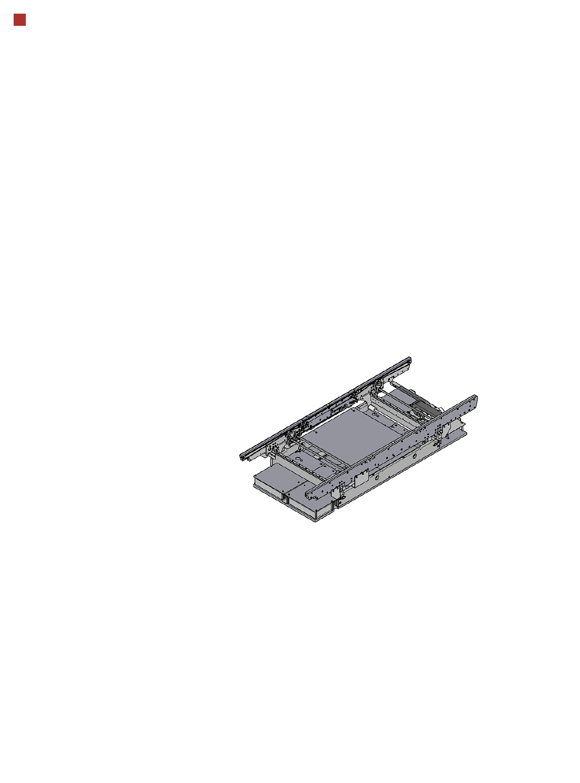
Single conveyor
On the single conveyor,
PCBs are moved one after
the other into the placement
machine and placed on a
conveyor lane. This con-
veyor variant is particularly
suitable for very wide PCBs.
Single conveyor
23
PCB conveyor SIPLACE SX1/SX2
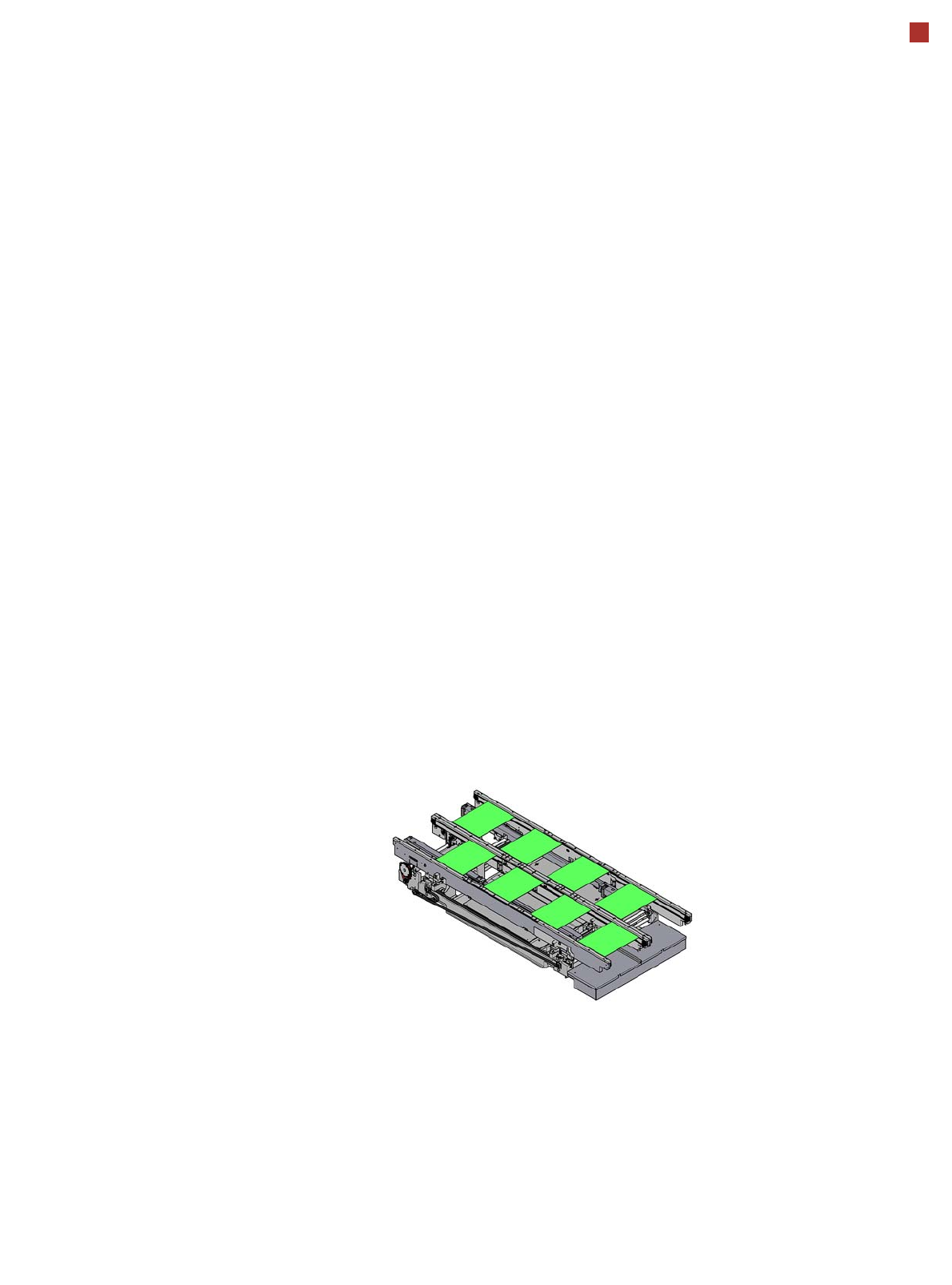
Flexible dual conveyor
Flexible dual conveyor
To keep the range of PCBs to
be processed as wide as
possible - whilst maintaining
maximum productivity - the
flexible SIPLACE dual con-
veyor allows you to choose
between single conveyor
mode and dual conveyor
mode. In the dual conveyor,
two boards are moved into
the placement machine and
placed either at the same
time (synchronous mode) or
alternatively (asynchronous
mode). This makes it possi-
ble to process the top and
bottom sides of a board in
one line.
Synchronous mode
In synchronous mode, two
PCBs are moved into the
placement position at the
same time. They are pro-
cessed as a common panel.
When using products with
widely differing placement
contents, common optimiza-
tion of the entire placement
content for both boards can
enhance performance.
Asynchronous mode
In asynchronous mode, only
one PCB is processed per
conveyor lane. At the same
time, another PCB in the sec-
ond conveyor lane is moved
into the placement position.
This saves the full conveying
time of one PCB, thus con-
siderably increasing perfor-
mance, particularly for PCBs
with a short cycle time. The
placement process starts as
soon as one PCB is trans-
ported into the processing
area.
I-Placement
In addition to synchronous
and asynchronous conveyor
mode, a new placement con-
cept has been developed for
the SIPLACE SX: I-Place-
ment. In this mode, the two
heads work simultaneously
and populate a PCB totally
independently of one
another. This further
increases the output.
The background: the place-
ment heads and component
feeder modules of the
SIPLACE SX have acceler-
ated component pickup to
such a degree that it is now
the transport path to the
board and not the pickup pro-
cedure which has become
the speed-restricting factor.
Flexible dual conveyor
Asynchronous placement mode
or I-Placement
24
PCB conveyor SIPLACE SX1/SX2
Technical Data
Single conveyor Flexible dual con-
veyor
Dual conveyor in single
conveyor mode
Standard dimensions
(length x width)
50 mm x 50 mm to
450 mm x 560 mm
a
a) When using boards with a width > 450 mm, make sure the peripheral module can also process the PCB width
concerned.
50 mm x 50 mm to
450mm x 260mm
50 mm x 50 mm to
450 mm x 460 mm
Dimensions with “Long
Board”option
(length x width)
50 mm x 50 mm to
850 mm x 560 mm
a
50 mm x 50 mm to
850mm x 260mm
50 mm x 50 mm to
850 mm x 460 mm
Stationary conveyor side Right, left or outer
Automatic electrical width
adjustment?
Yes
PCB thickness
Standard
"Thick board" option
0.3 mm to 4.5 mm
2.0 mm to 6.5 mm
Clamping length of board 450 mm
Space for positioning
support pins
440 mm
PCB warpage see page 26
PCB weight
b
Standard
b) The board weight value refers to the weight of the board plus the weight of the components.
max. 2.0 kg max. 1.0 kg max. 2.0 kg
Clearance on PCB
underside
c
c) The free positioning of board supports is limited by the stop bar.
25 mm
PCB transport height
Option
Standard
SMEMA option
900 mm
930 mm
950 mm
Interface type
Standard
Option
SMEMA
Siemens
Component-free PCB
handling edge
3 mm
PCB changeover time
Single conveyor
Dual conveyor
d
d) 0 seconds in asynchronous mode, otherwise 1.5 seconds.
< 1.5 seconds
0 seconds
Important information for machines in combination with SIPLACE SX2/SX1:
When setting up a machine (S; F, HS, HF, X or D series) next to a SIPLACE SX1/SX2, take note of the limited space
between the two machines. In these cases, you will need a 0.5 m conveyor between the SIPLACE SX1/SX2 and the
adjacent machines.