ASM-X-Spec-SX12V2-EN-DMS.pdf - 第25页
25 SIPLACE SX PCB Conveyor I-Placement Alternating placement mode Alternating or I-Placement mode Distance of outer conveyor edges: 560 mm, 2 lanes, outer conveyor edges fixed Alternating placement mode Distance of outer…
24
PCB conveyor SIPLACE SX1/SX2
Technical Data
Single conveyor Flexible dual con-
veyor
Dual conveyor in single
conveyor mode
Standard dimensions
(length x width)
50 mm x 50 mm to
450 mm x 560 mm
a
a) When using boards with a width > 450 mm, make sure the peripheral module can also process the PCB width
concerned.
50 mm x 50 mm to
450mm x 260mm
50 mm x 50 mm to
450 mm x 460 mm
Dimensions with “Long
Board”option
(length x width)
50 mm x 50 mm to
850 mm x 560 mm
a
50 mm x 50 mm to
850mm x 260mm
50 mm x 50 mm to
850 mm x 460 mm
Stationary conveyor side Right, left or outer
Automatic electrical width
adjustment?
Yes
PCB thickness
Standard
"Thick board" option
0.3 mm to 4.5 mm
2.0 mm to 6.5 mm
Clamping length of board 450 mm
Space for positioning
support pins
440 mm
PCB warpage see page 26
PCB weight
b
Standard
b) The board weight value refers to the weight of the board plus the weight of the components.
max. 2.0 kg max. 1.0 kg max. 2.0 kg
Clearance on PCB
underside
c
c) The free positioning of board supports is limited by the stop bar.
25 mm
PCB transport height
Option
Standard
SMEMA option
900 mm
930 mm
950 mm
Interface type
Standard
Option
SMEMA
Siemens
Component-free PCB
handling edge
3 mm
PCB changeover time
Single conveyor
Dual conveyor
d
d) 0 seconds in asynchronous mode, otherwise 1.5 seconds.
< 1.5 seconds
0 seconds
Important information for machines in combination with SIPLACE SX2/SX1:
When setting up a machine (S; F, HS, HF, X or D series) next to a SIPLACE SX1/SX2, take note of the limited space
between the two machines. In these cases, you will need a 0.5 m conveyor between the SIPLACE SX1/SX2 and the
adjacent machines.
25
SIPLACE SX PCB Conveyor
I-Placement
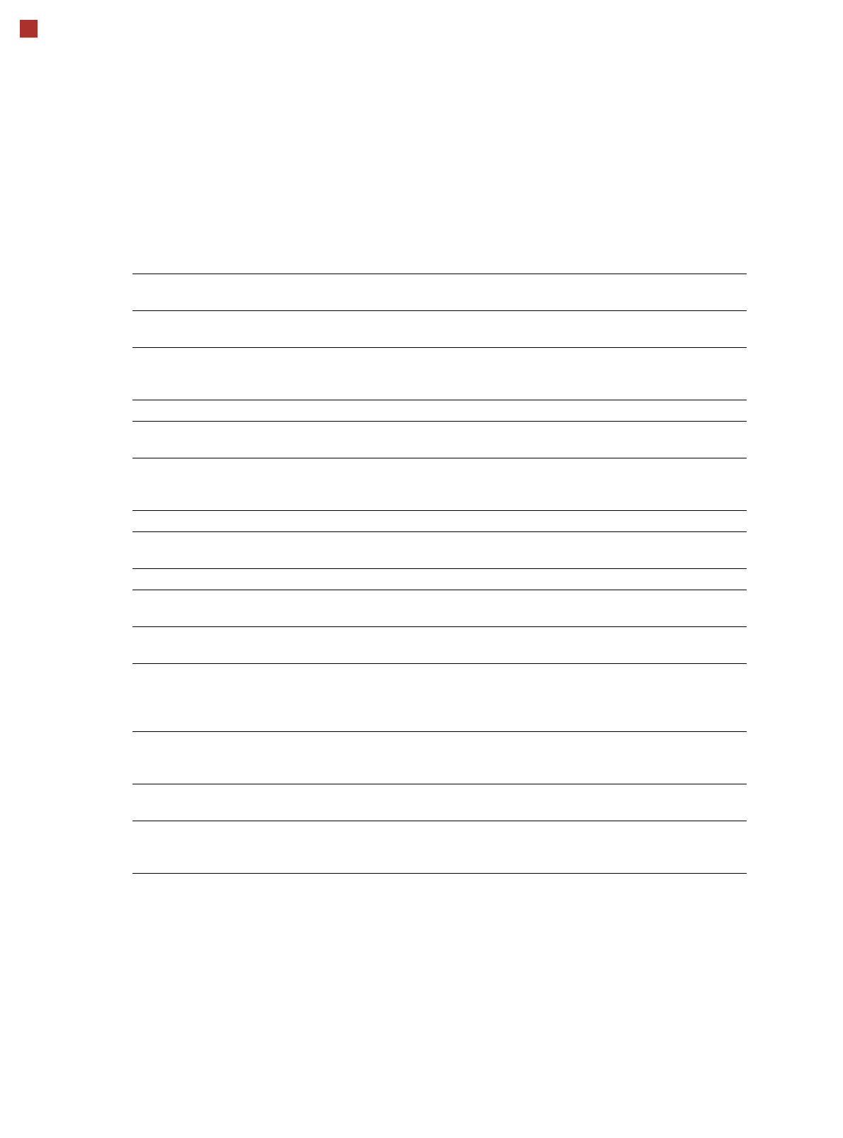
Alternating placement mode
Alternating or
I-Placement mode
Distance of outer conveyor
edges: 560 mm, 2 lanes, outer
conveyor edges fixed
Alternating placement mode
Distance of outer conveyor
edges: 560 mm, 2 lanes, right
conveyor edges fixed
a
Alternating placement mode
Distance of outer conveyor
edges: 560 mm, dual conveyor
in single conveyor mode, right
conveyor edge fixed
a
max. 260
Movable conveyor side
Stationary conveyor side
a) Only the settings with fixed conveyor edge on the right are shown. A setting with the stationary conveyor edge
on the left is also possible. All dimensions in millimeters.
max. 260
281
560
min. 35
281
179
max. 260
281
min. 35
max. 260
560
max. 460
Adjustable side position and max. board width
Side position Max. board width
234.2 mm 216 mm
254 mm 236 mm
259.7 mm 242 mm
268 mm 250 mm
281 mm 260 mm
Customized (anything up to max. 281 mm) 260 mm
26
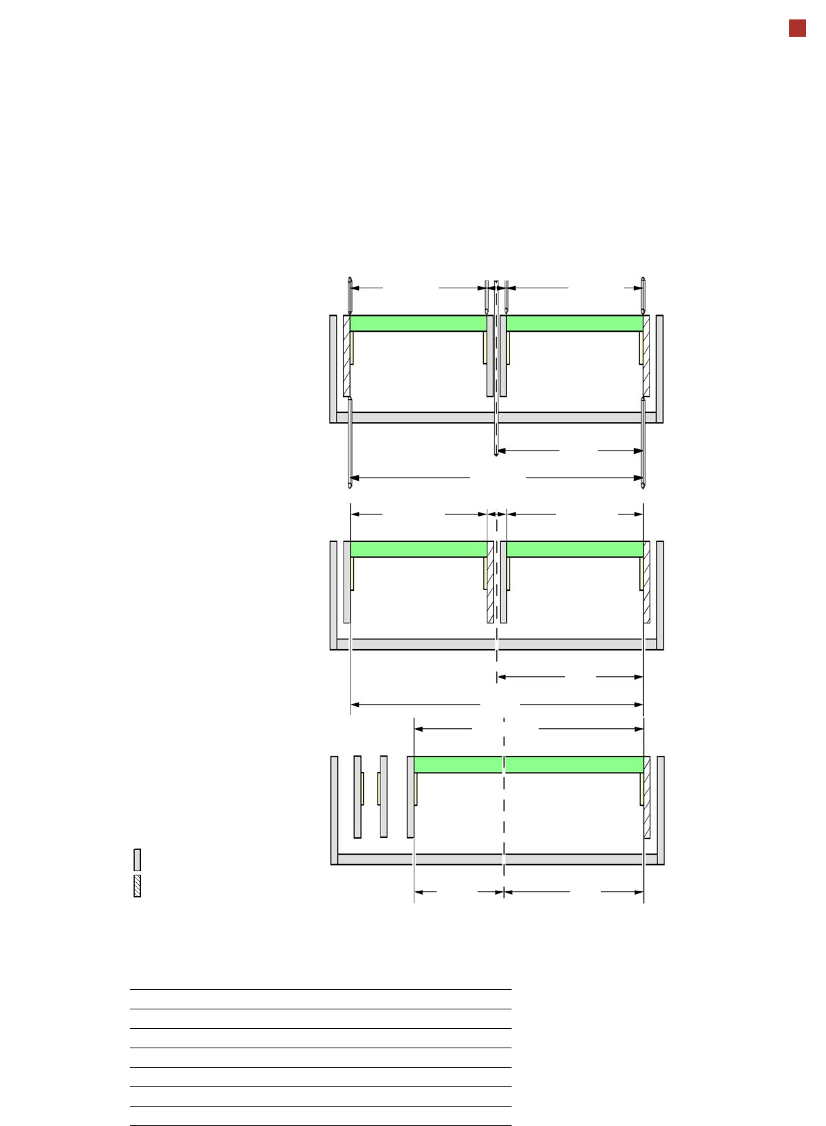
PCB warpage
PCB warpage across the direction of travel
max. 1 % of the PCB diagonal, but not
exceeding 2 mm
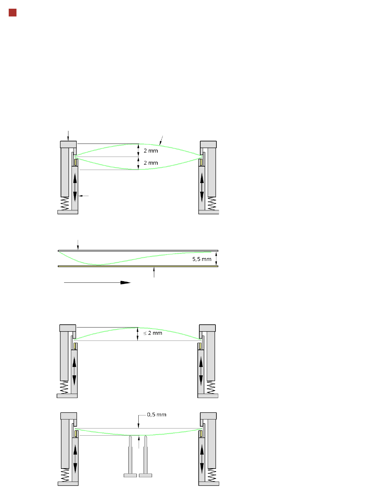
PCB warpage on the conveyor
PCB warpage during placement
PCB transport direction
PCB warpage downwards max. 0.5 mm
Use the magnetic pin supports, to achieve
this value.
Conveyor belt
Fixed clamped edge
PCB warpage in direction of travel
+ PCB thickness < 5.5 mm
Fixed clamped edge
Movable clamping device
When there is warpage under 2 mm, the
inkspots in the center of the board are also
within the focus of the digital camera. When
all the tolerances are taken into account,
this value is reduced to 1.5 mm.
You should also note that the warpage
reduces the component height.
Magnetic pin support
PCB