ASM-X-Spec-SX12V2-EN-DMS.pdf - 第26页
26 PCB warpage PCB warpage across the directio n of travel max. 1 % of the PCB diagonal, but no t exceeding 2 mm PCB warpage on the co nveyor PCB warpage during placement PCB transport direction PCB warpage d ownwards ma…
25
SIPLACE SX PCB Conveyor
I-Placement
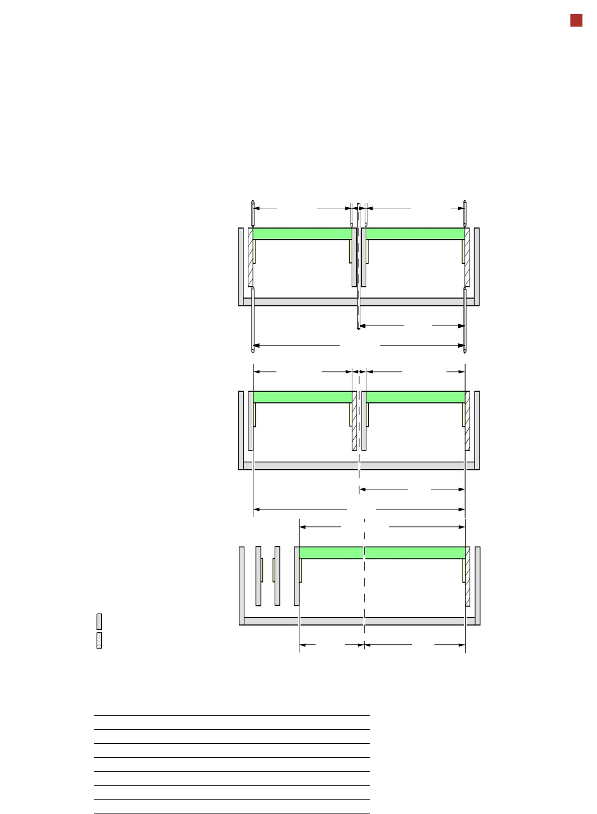
Alternating placement mode
Alternating or
I-Placement mode
Distance of outer conveyor
edges: 560 mm, 2 lanes, outer
conveyor edges fixed
Alternating placement mode
Distance of outer conveyor
edges: 560 mm, 2 lanes, right
conveyor edges fixed
a
Alternating placement mode
Distance of outer conveyor
edges: 560 mm, dual conveyor
in single conveyor mode, right
conveyor edge fixed
a
max. 260
Movable conveyor side
Stationary conveyor side
a) Only the settings with fixed conveyor edge on the right are shown. A setting with the stationary conveyor edge
on the left is also possible. All dimensions in millimeters.
max. 260
281
560
min. 35
281
179
max. 260
281
min. 35
max. 260
560
max. 460
Adjustable side position and max. board width
Side position Max. board width
234.2 mm 216 mm
254 mm 236 mm
259.7 mm 242 mm
268 mm 250 mm
281 mm 260 mm
Customized (anything up to max. 281 mm) 260 mm
26
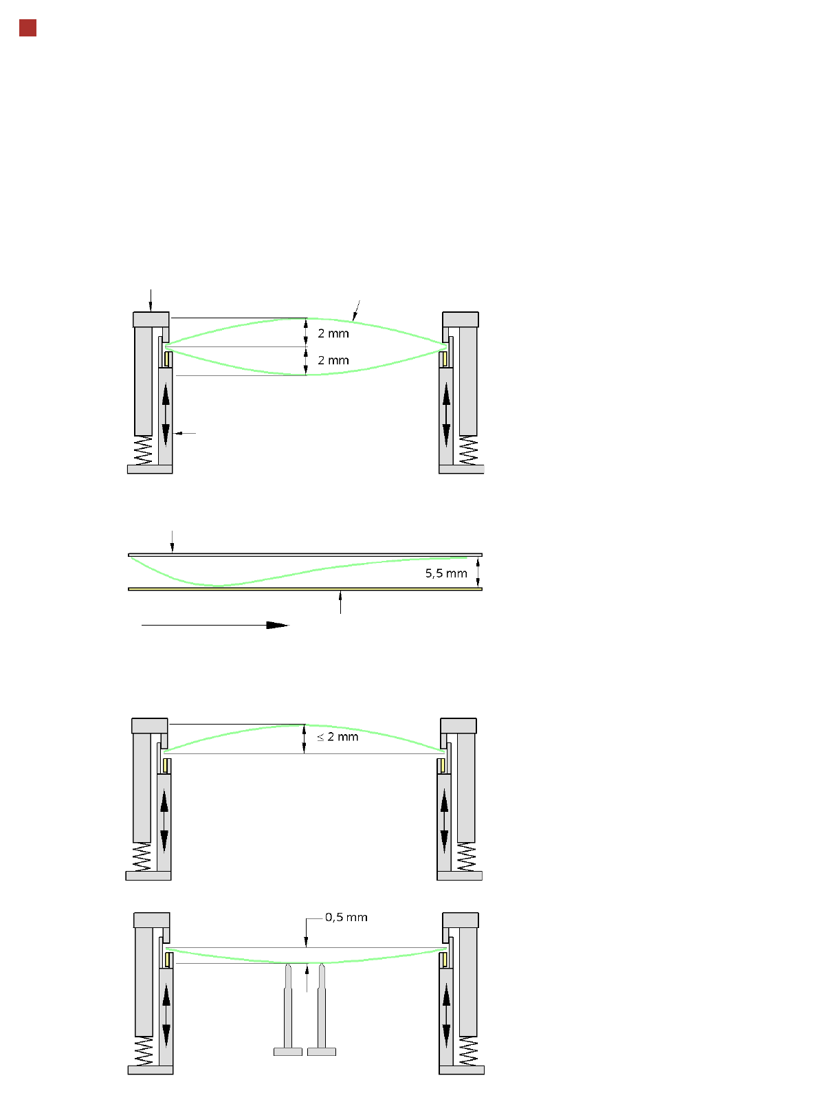
PCB warpage
PCB warpage across the direction of travel
max. 1 % of the PCB diagonal, but not
exceeding 2 mm
PCB warpage on the conveyor
PCB warpage during placement
PCB transport direction
PCB warpage downwards max. 0.5 mm
Use the magnetic pin supports, to achieve
this value.
Conveyor belt
Fixed clamped edge
PCB warpage in direction of travel
+ PCB thickness < 5.5 mm
Fixed clamped edge
Movable clamping device
When there is warpage under 2 mm, the
inkspots in the center of the board are also
within the focus of the digital camera. When
all the tolerances are taken into account,
this value is reduced to 1.5 mm.
You should also note that the warpage
reduces the component height.
Magnetic pin support
PCB
27
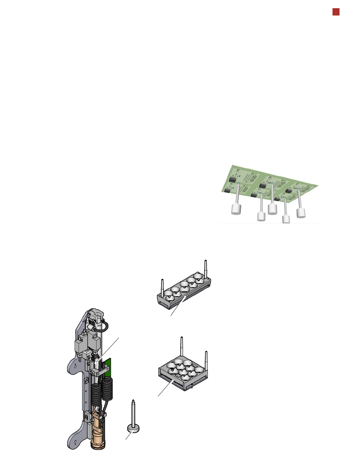
Smart Pin Support
General
Wide boards tend to deflect
during placement such that,
under certain circumstances,
the components can no lon-
ger be placed with the
desired accuracy. Highly
curved PCBs also affect the
placement accuracy. This
problem can be easily recti-
fied by fitting support pins on
the lifting table.
Smart Pin Support
The support pins are auto-
matically placed on the lifting
table with the help of the
Smart Pin Support option. A
gripper unit is used to pick
the support pins up from spe-
cial magazines and place
them in the prescribed posi-
tions.
Before you place a smart
support pin, the placement
area is cleaned from any
contaminants with a gentle
blast of air. In addition, the
correct position of the sup-
port pins is checked after
placement, with the PCB
camera.
Magazines
There are two different mag-
azines available for auto-
matic changeover to max. 10
support pins in the various
machine configurations.
These magazines are fixed
to a magazine holder and are
fitted to the component trol-
ley docking unit.
Programming
The positions of the support
pins in the machine can be
defined for each board side,
in the SIPLACE Pro Board
Editor.
A 3D diagram of the board
and support pins allows you
to detect and avoid potential
collisions with components,
even during stepped trans-
portation of extra long
boards.
Magazine L 10
Magazine Q 10
Gripper unit
Support pin