SOM-1619-001.pdf - 第20页
20 Tg0590-PM-SO Fig. 7 T each Operation in the case of 1-Pt 0301-002 5. Placement Position T each T eaching Operation for 1 Point The movement is limited to the position in which the four corners of the display are overl…
19 Tg0590-PM-SO0301-002
5. Placement Position Teach
Teaching at diagonal 2 point of component
Select "Diagonal 2pt" (Opposite Angles of Component) in the
"Teach Point" box.
In 2-point teaching, when teaching of the first point is com-
pleted, the cursor shifts to the second point automatically.
(5) Check that there is a cursor on the step to be taught.
(6) Check the Teach Point setting and press the [TEACH] button *8.
Then, within 2 seconds, press the [ENABLE] button on the
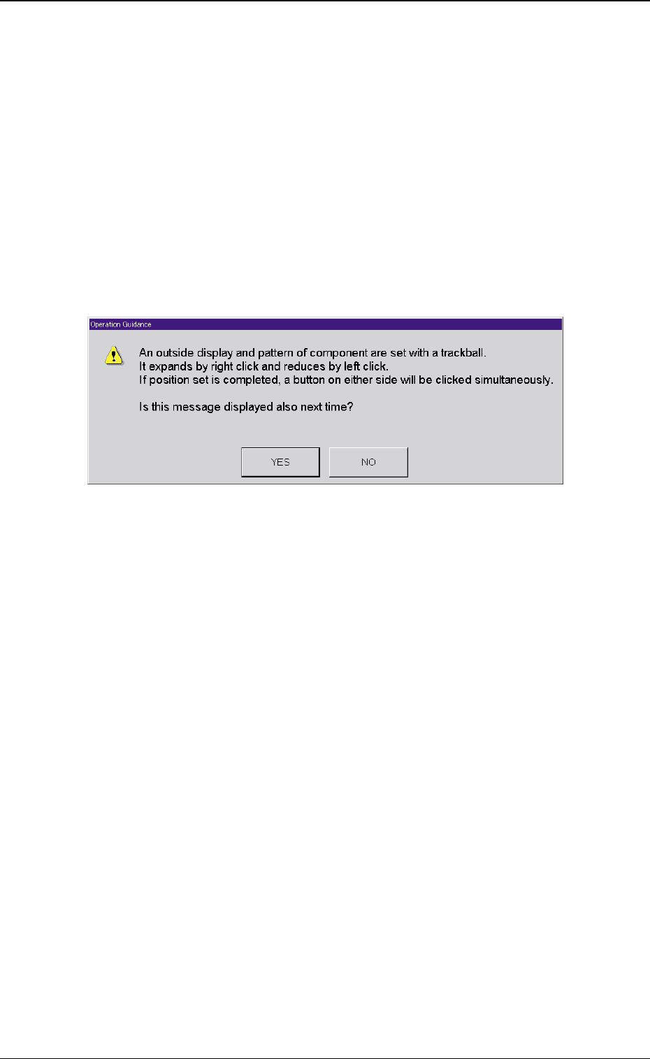
operation panel. The "Operation Guidance" window is indicated.
Fig. 6 "Operation Guidance" Window
(7) Press the [YES] button in the "Operation Guidance" window.
If the "Operation Guide" is not to be displayed a second time,
press [NO].
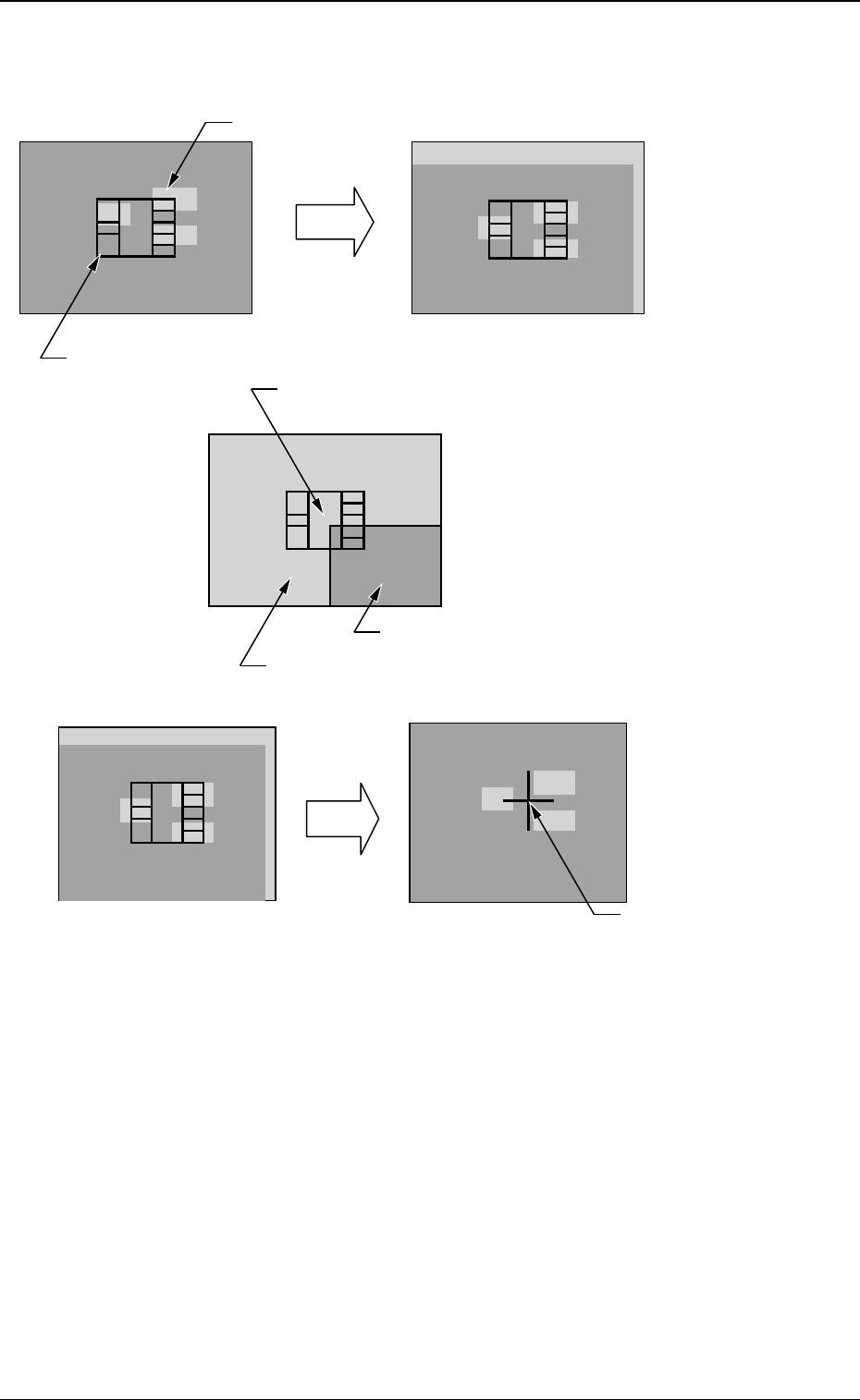
(8) Match the component outer shape image within the recognition
area and the PCB pattern entered in the recognition memory
image using the pointing device.
When the position is set, press the left and right buttons at the
same time on the pointing device to define the position.
Operation of the Pointing Device
Joy Stick : Movement of the X/Y table (PCB
Pattern)
Right Click : Enlargement of Image
Left Click : Reduction of Image
Click on the Right and Left at the Same Time
: Positioning Completion
20 Tg0590-PM-SO
Fig. 7 Teach Operation in the case of 1-Pt
0301-002
5. Placement Position Teach
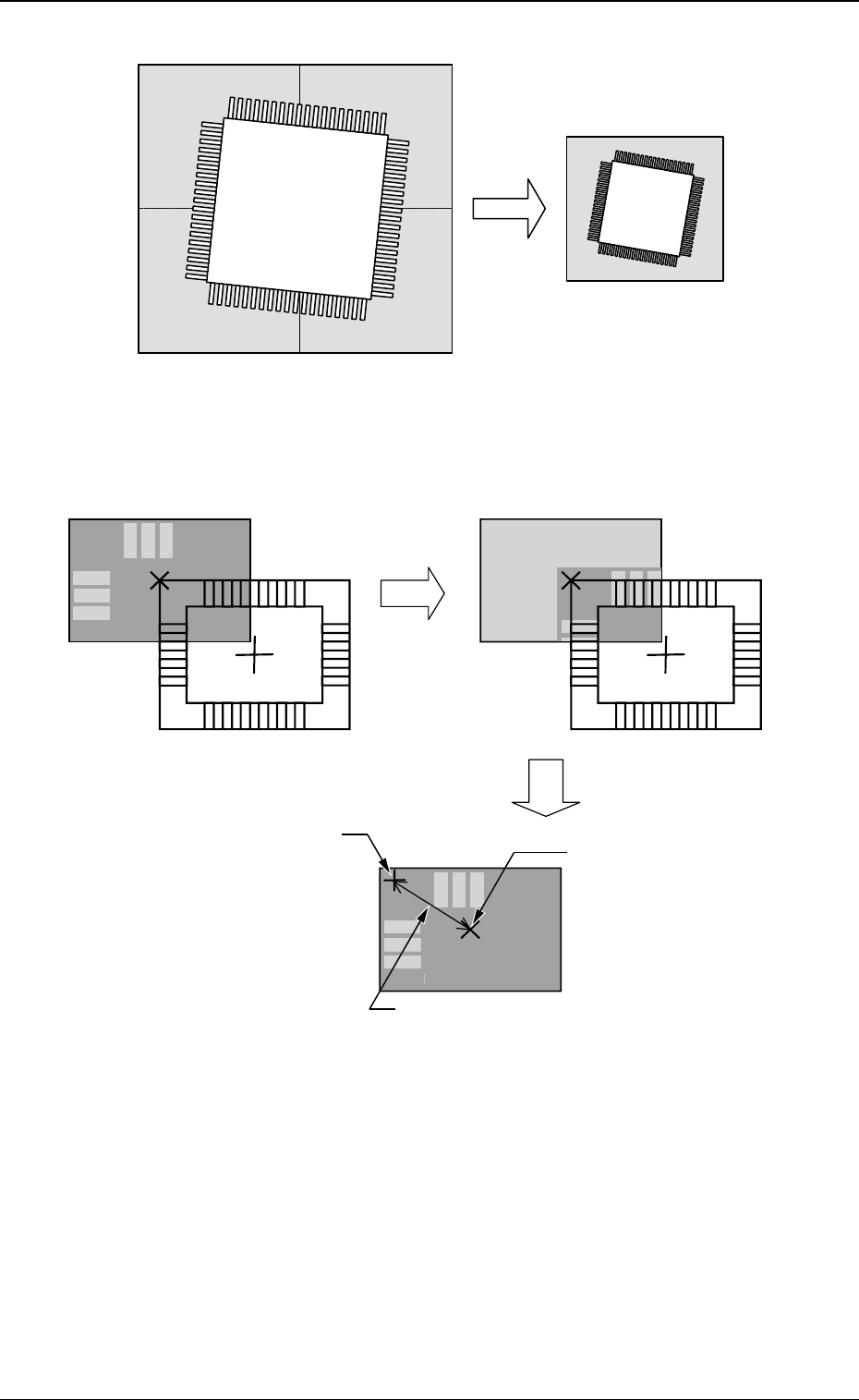
Teaching Operation for 1 Point
The movement is limited to the position in which the four corners
of the
display are overlapped with the monitor center.
Image inside the View
PCB Pattern
Image outside the View
Component Outer Shape Image
Move the X/Y table by using the pointing device.
Move
C=MARK X=OOO Y=OOO
Deciding
the Position
Press the right and left buttons at the same time on the pointing device.
The decided position is
indicated as a blue cross.
1- Pt Teach
21 Tg0590-PM-SO
Image 1
Image 4Image 3
Image 2
Synthesized Image
Divided Image (Example of Four Images Synthesized)
0301-002
5. Placement Position Teach
Fig. 7-1 Example of Image Synthesis in Divided Image Shooting
Fig. 8 Teach Operation in the case of Diagonal 2-Pt
Teach Operation for Diagonal 2 Points
C
=
M
A
R
K
X=
OOO
Y=
OOO
Teach
D
ecidin
g
the Position
D
ispla
y
Cente
r
It is not actually indicated
.
The distance from the displa
y
center is shown
.
The decided
p
osition is
in
d
i
ca
t
ed
as
a
b
l
ue
c
r
oss.