SOM-1619-001.pdf - 第7页
7 Tg0590-PM-SO Fig. 2 "PCB Origin Offset T each" T ab Sheet ("Designation of Placement" is selected) 4.1 " PCB Origin Offset T each" T ab Sheet • • • • • Sheet Layout When the [PCB Origin Of…
6 Tg0590-PM-SO
4. PCB Origin Offset Teach
The PCB origin offset teaching operation is performed.
The PCB origin offset is the datum designating the reference for all
coordinate data set on the pattern program.
This offset is used for the pattern data where the PCB on the mother
board has an edge (ear) with no pattern, or when the actual pattern is
not evenly dispersed.
0301-002
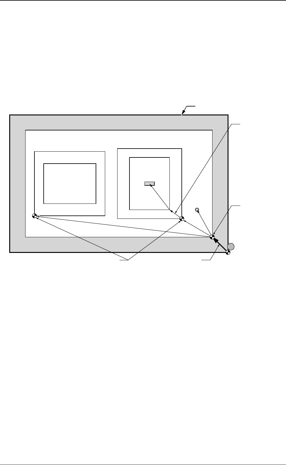
Fig. 1 Items to be Taught in PCB Origin Offset Teach Operation
4. PCB Origin Offset Teach
Unit Pattern Angle: 270
°
Unit Pattern Angle: 0
°
Pattern Domain
PCB Outermost Shape
Component
Placement
Position
Whole PCB
Recognition
Mark
O
1
O
2
PCB Origin Offset
Outline
Positioning Pin
PCB Positioning
Reference
Pn
Pattern Origin
Unit Control
Offset
PCB Origin
7 Tg0590-PM-SO
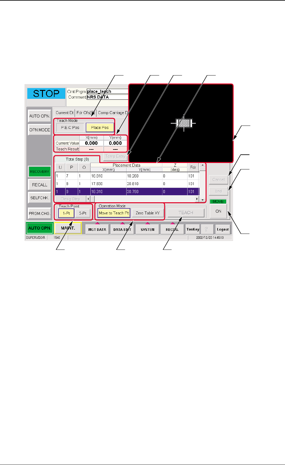
Fig. 2 "PCB Origin Offset Teach" Tab Sheet ("Designation of Placement" is selected)
4.1 " PCB Origin Offset Teach" Tab Sheet
••
••
• Sheet Layout
When the [PCB Origin Offset Teach] tab is pressed on the "RECOV-
ERY" window, the following window appears.
0301-002
4. PCB Origin Offset Teach
••
••
• Sheet Composition
*1 Teach Mode
The mode for P.E.C. recognition offset teach is selected.
P.E.C. Pos
When the P.E.C. recognition mode global is implemented,
the PCB origin offset teach operation is performed (using
the P.E.C. recognition mark #1). When the P.E.C. recogni-
tion mark is selected, items *6 and *7 are not displayed.
*2*1
*3 *6
*9
*8
*11
*10
*4
*7 *5

8 Tg0590-PM-SO0301-002
4. PCB Origin Offset Teach
Place Pos
The PCB origin offset teach operation is performed using the
placement position #1 or any other placement positions.
(a) The selection of the P.E.C. recognition mark or
placement position will be automatically per-
formed according to the pattern program set-
ting.
(b) When the P.E.C. recognition mode global
function is used, the teaching point is at the
global recognition point #1. However, if the
teaching is not available because of the degra-
dation of a P.E.C. recognition mark on the PCB
for which the teaching is performed, then select
the placement position for the teaching point.
(c) When the P.E.C. recognition mode global
function is not used, the teaching point is at the
placement position #1. If the teaching operation
in this position is difficult, then select another
placement position.
*2 Placement Data
The pattern program position presently referred and when
position resultant from the teaching are indicated.
*3 [Temp Entry] Button
The position which is being taught is temporarily entered.
*4 Operation Mode
When the operation mode is selected and the "Move" [ON]
button is pressed, the X/Y table is moved to the designated
position.
Move to Teach Pt
The X/Y table is moved to the position set in the P.E.C.
recognition offset operation.
Zero Table XY
The X/Y table is returned to the origin.
TB01
Pattern Program
Setting
Teaching Point
Enable Global Recognition Point #1 or Designated Placement
Position (Initial Value
: Placement Position #1)
PEC
Recognition
Mode Global
Disable Designated Placement Position (Initial Value : Placement
Position #1)