80S20 circuit.pdf - 第71页
3 SIPLACE 80S-20 Circuit Diagrams 71 00321480-020701 TD3 Servo unit, viewed from the front (Sh . 1 of 2) 18 004 002 AA - BBBB - C CCC 00321480-0 2 24V 6L+ 009 008 12V 1L+ GND 001 8 A B C D E F F E D 4 1 L1/L2 L3/L4 L5/L6…
3 SIPLACE 80S-20 Circuit Diagrams 70
00321480-020701LD3 80S20 servo unit (Sh. 2 of 2)
=
SIEMENS AG
+
DP1-axis
Backplane
(Gantry 1)
Ballast circuit Power supply unit (+/-15V)
Anti-crash board
Backplane
Star
(Gantry 2)
Servoverstaerker
Star
(Gantry 2)
Servoverstaerker
Z-axis
(Gantry 2)
Backplane
(Gantry 2)
Z-axis
Backplane
DP1-axis
(Gantry 2)
Servoverstaerker
DP1-axis
(Gantry 2)
PL EA1 E
F
8
A9
(vo)
X4vo
X1
X1
X13
A16
A8
X4vr
3L+
X3vr
X1vr
X1
2
D
C
5
2
(vr)
432
A10
71
876
65
A
BB
C
D
X1
X1vo
X3vo X2vp
A27
2L+/5L+
A
F
X4vp
X11
A15
X1
X12
A17
X2vo
12
X1
E
X3vc
X1vc
43
A25
(vc)
X1
A5
X2vc
X2vr
A26
3L+
X3vp
X1vp
(vp)
E
A3
X2vf
A21
3L+
(vd)
X4vd X3vd
X1vd
X1
A4
X2vd
A22
2L+/5L+
X4vc
A20
3L+
(vf)
Deu
Deu
Deu
02
07
01
22.09.98
22.09.98
22.09.98
22.09.98
Haas
#
00321480-020701LD3
X4vf X3vf
X1vf
X1
Date
Check.
Author
Creat. byCreat. f.Orig.NameModified DateStatus Stand.
Sh.
Sheet
SMD Placement System SIPLACE 80S20
Document status
Product status
Function status
80S20 servo unit
SP-head
SP-head
SP-head
Tachometer
Voltage
Voltage
Nominal values
Motor
Nominal values
Motor
Tachometer
Voltage
Nominal values
Motor
Tachometer
Tachometer
Voltage
Voltage
Motor
Tachometer
Voltage
Motor
Nominal values
Nominal values
Motor
Tachometer
Nominal values
SP-head
SP-head
SP-head
Servoverstaerker
(Gantry 1)
Star
Backplane
Star
(Gantry 1)
Backplane
Z-axis
(Gantry 1)
Servoverstaerker
(Gantry 1)
Z-axis
(Gantry 1)
Servoverstaerker
DP1-axis
3 SIPLACE 80S-20 Circuit Diagrams 71
00321480-020701TD3 Servo unit, viewed from the front (Sh. 1 of 2)
18
004002
AA - BBBB - CCCC
00321480-02
24V6L+
009008
12V
1L+
GND
001
8
A
B
C
D
E
FF
E
D
4
1
L1/L2
L3/L4
L5/L6
L7/L8
23456
3
2
2L+/5L+
2L+
1
SIEMENS PLEA
2
005
86
003
5V
006
1
B
5 7
007
7
Deu
Deu
Deu
02
07
01
22.09.98
22.09.98
22.09.98
22.09.98
Haas
#
00321480-020701TD3
7L+
40
C
A
PL EA1 E
Date
Check.
Author
Creat. byCreat. f.Orig.NameModified DateStatus Stand.
Sh.
Sheet
SMD Placement System SIPLACE 80S20
Document status
Product status
Function status
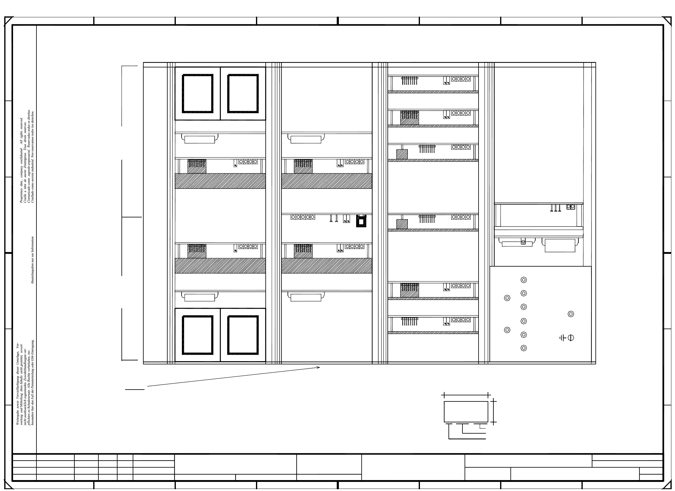
Please note :
apply the following labels:
On the outside (flush with the front plate)
Servo unit (viewed from the front)
B: inspection label Identification: testing engineer, month, year
A: identification label, assembly inscription acc. to VA-F-510-001
Date (year/month/day) acc. to SN 01007
Manufacturer/location acc. to SN 37040
Series number
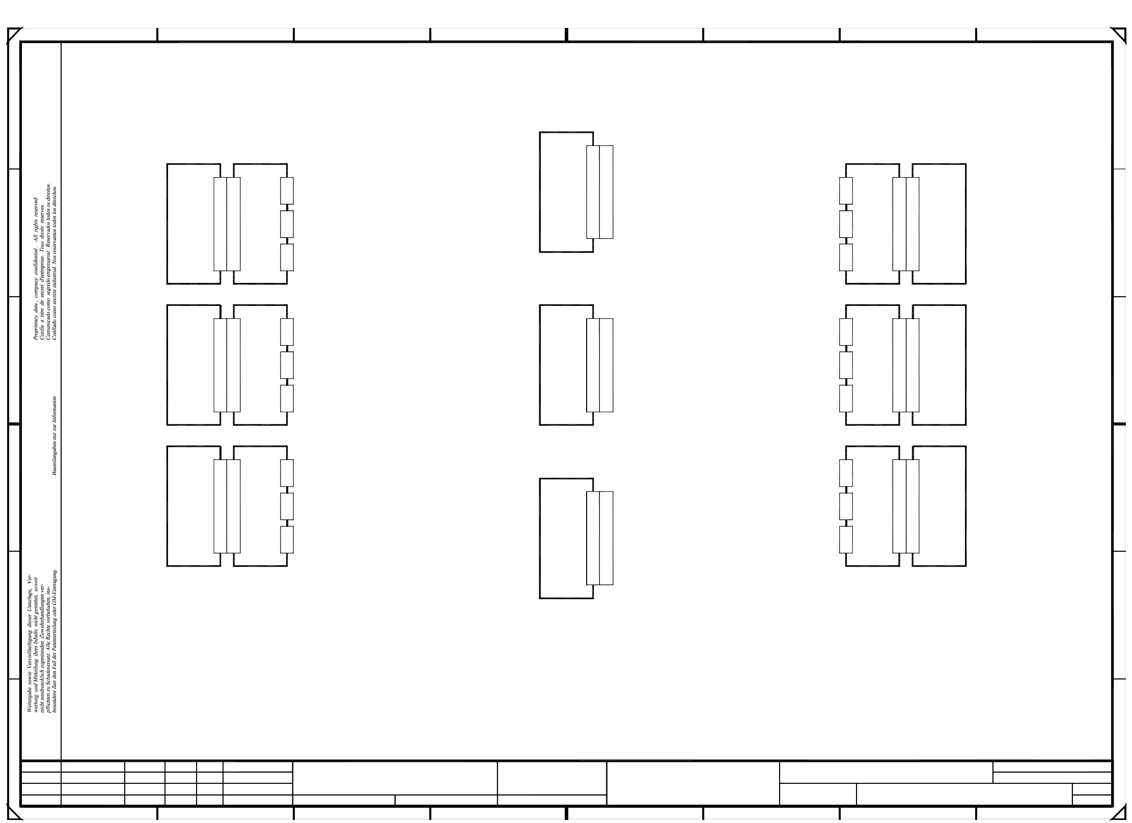
Gantry IIGantry I
A28 fan unit
Dynamic brake Y I A12
Y-axis I A2
Y-axis II A7
Dynamic brake Y I A14 Dynamic brake X II A13
Anti-crash board A15
X-axis II A6
X-axis I A1
Dynamic brake X I A11
DP1-axis I A3
Z-axis I A4
Star I A5
Star II A10
Z-axis II A9
DP1-axis II A8
A16 ballast circuit
Power supply unit A17
=
SIEMENS AG
+
3 SIPLACE 80S-20 Circuit Diagrams 72
00321480-020701TD3 80S20 servo unit (Sh. 2 of 2)
PL EA1 E
E
F
TDS120/1D
3
2
A
B
C
45 86
-15V
F
4
2
123
+15V
+15V
GND
-15V
D
AGND
A
B
C
D
E
TDS120/25Y
678
12
5
7
Deu
Deu
Deu
02
07
01
22.09.98
22.09.98
22.09.98
22.09.98
Haas
#
00321480-020701TD3
Date
Check.
Author
Creat. byCreat. f.Orig.NameModified DateStatus Stand.
Sh.
Sheet
SMD Placement System SIPLACE 80S20
Document status
Product status
Function status
IA Motor manipulated variable (current contr. output)
Is Nominal current (speed controller output)
Ns Nominal speed
Ie Nominal power input
Ta tachometer (real tachometer voltage)
Ii Actual current value
Ss Sensor-stop signal
0V Amplifier electronics GND
80S20 servo unit
(Assemblies overview)
Y-axis servo board
X-axis servo board
Output stage, enable
I r.m.s limiting
P-gain
Fault
Tachometer
Ready status
(I² x t signal)
TDS120/12,5X
X-axis, gantry I
Y-axis, gantry I
X-axis, gantry II
Distance sensor
Y-axis, gantry II
Analog voltage, distance sensor
Zero point, distance sensor
Gain, distance sensor
Reset button
Anti-crash board
TBS120/2,5SStar-axis servo board
Power supply unit
I r.m.s limiting
Ready status
Output stage, enable
Fault
(I² x t signal)
max. current
10V correspond
to device
Scaling:
max. motor volt.
Scaling:
10V correspond
0V Reference potential
Spare
Is (U) Current nom. value
Is (W) Current nom. value
Vnom (W) Current regulator output
Iact (U) Current actual value
Iact (W) Current actual value
Vnom (U) Current regulator output
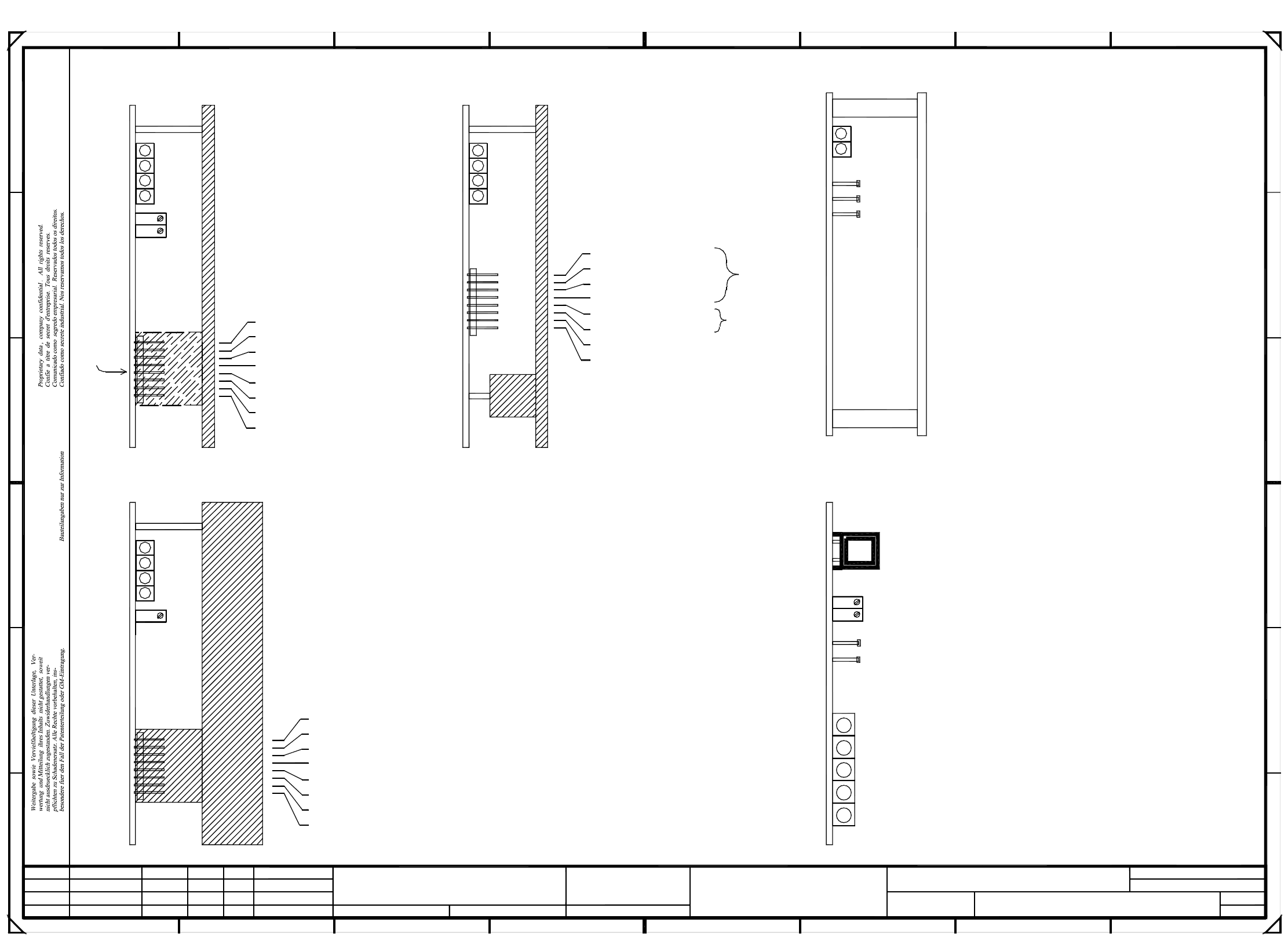
Heat sink installed in Z-axis only
Please note:
IA Motor manipulated variable (current contr. output)
Ta tachometer (real tachometer voltage)
Is Nominal current (speed controller output)
0V Amplifier electronics GND
Ie Nominal power input
Ss Sensor-stop signal
Ii Actual current value
Ns Nominal speed
P-gain
Ready status
Fault
I r.m.s limiting
Output stage, enable
Tachometer
(I² x t signal)
TDS120/A2,5Z
DP1-axis servo board
Z-axis servo board
=
SIEMENS AG
+