80S20 circuit.pdf - 第78页
3 SIPLACE 80S-20 Circuit Diagrams 78 00321693-030101 TD3 80S20 servo unit, basic modu le, viewed from the front (Sh. 2 of 3) L7/L8 L5/L6 X8 3 1 F F 3 2 4 1 8 004 24V 1L+ 7 56 7 C 001 8 GND X12 A26 A25 L3/L4 E 003 56 B 00…
3 SIPLACE 80S-20 Circuit Diagrams 77
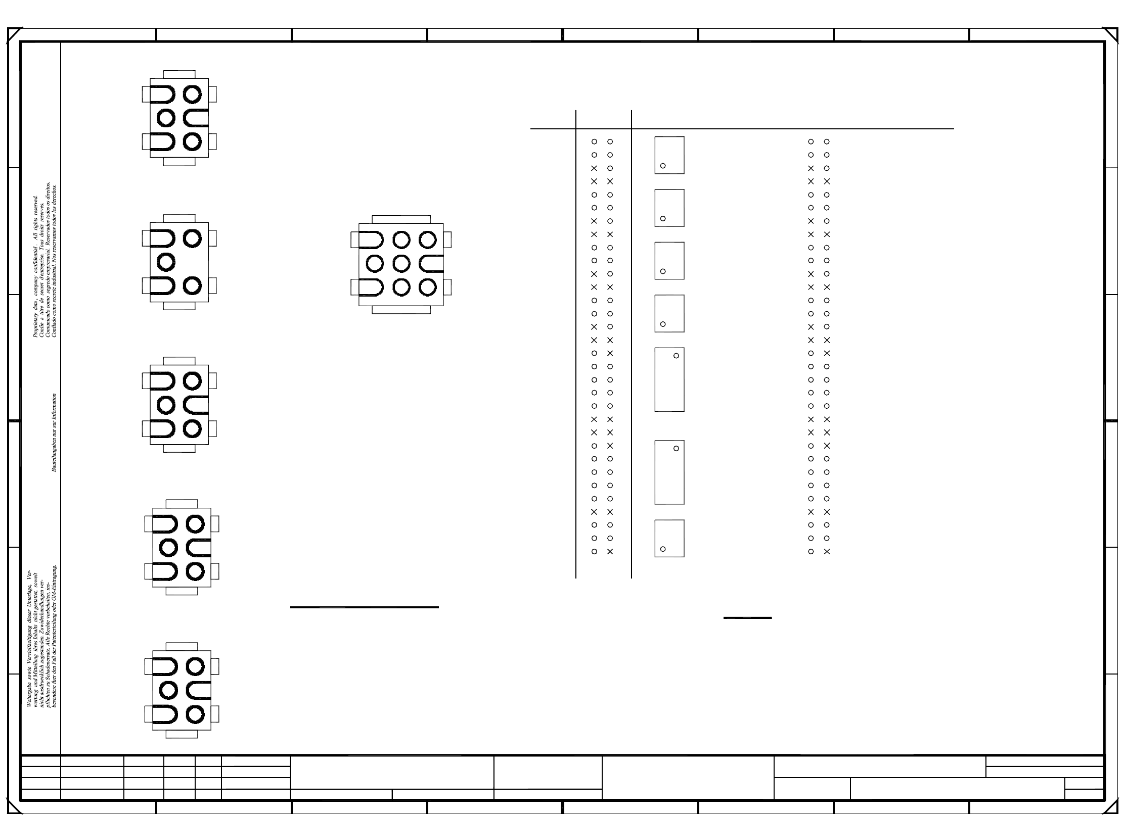
00321693-030101TD3 80S20 servo unit, basic module, plug assignment (Sh. 1 of 3)
=
SIEMENS AG
+
b
7
6
T
X11e
X11f
8
1L+
12
5
25
24
23
X4
1
22
30.09.98
01
01
03
Deu
Deu
Deu
n.c.
n.c.
n.c.
Date
Check.
Author
Creat. byCreat. f.Orig.NameModified DateStatus Stand.
Sh.
Sheet
SMD Placement System SIPLACE 80S20
Document status
Product status
Function status
80S20 servo unit, basic module
(Plug assignment)
All pins marked with a cross
have to be cut out.
Please note!
Connector designation
Female connectors: 0.5-2.1mm²
Male connectors: 0.5-2.1mm²
Pin 4-6 Buchsenkontake 0,5-2,1mm²
Female connectors: 0.5-2.1mm²
Pins 1-3: male connector, 0.5-2.1mm²
Male connectors: 0.5-2.1mm²
Female connectors: 0.5-2.1mm²
zwPin
Tachometer -
Axis enable
Tachometer -
Axis enable
Tachometer -
Axis enable
Tachometer -
Axis enable
Anti-crash prox. switch 2, X-axis
Anti-crash prox. switch 1, X-axis
Anti-crash prox. switch 2, Y-axis
Anti-crash prox. switch 1, Y-axis
Distance sensor
Anti-crash prox. switch 1, X-axis
Anti-crash prox. switch 2, X-axis
Anti-crash prox. switch 1, Y-axis
Anti-crash prox. switch 2, Y-axis
Distance sensor Distance sensor
"Crash" signal for S5 ->
Distance sensor
"Crash" signal for S5 ->
Axis Enable (+15V)
Tachometer +
Axis Enable (+15V)
Tachometer +
Axis Enable (+15V)
Tachometer +
Axis Enable (+15V)
Tachometer +
PL EA1 E
30.09.98
30.09.98
00321693-030101TD3#
Haas
30.09.98
5
4
2
6
X3
1L-
M+
*
1
3
5
4
2
6
X14
*
7L+
+15V
2L+
1L-
+5V
+24V7L+
6L+
*
1
3
4
2
6
X4
1L-
F
E
n.c.
n.c.
6
D
C
B
A
3
5
4
2
6
X5/X70
T+
T-
M-
M+
3
X6/X71
T+
T-
M-
M-M+
1
3
1234
n.c.
n.c.
7
6L++24V
+5V
8
931L-
2L+/5L+
+12V7L+
6L+
*
1
A
B
C
D
E
F
10
11
key
9
18
20
21
19
17
16
15
key
6
n.c.
n.c.
n.c.
*
1
3
5
4
2
6
n.c.
n.c.
n.c.
a
n.c.
n.c.
1L+1L+
1L+
8
12345 78
30
29
28
27
26
T
6
X11c
2
1
56
X11d
2
1
56
X11g
2
X11a
2
key
n.c.
n.c.
n.c.
X14
5
1L+
X2
2L+
1
56
X11b
2
4
key
+5V
-15V
1
2
1
3
*
32
31
2
T
56
10
1
T
T
2
+15V
10
+24V
key
key
X3
key
7
1
2
4
6
X6/X71
1
n.c.
X2
13
14
X5/X70
1
9
5
9
*
n.c.
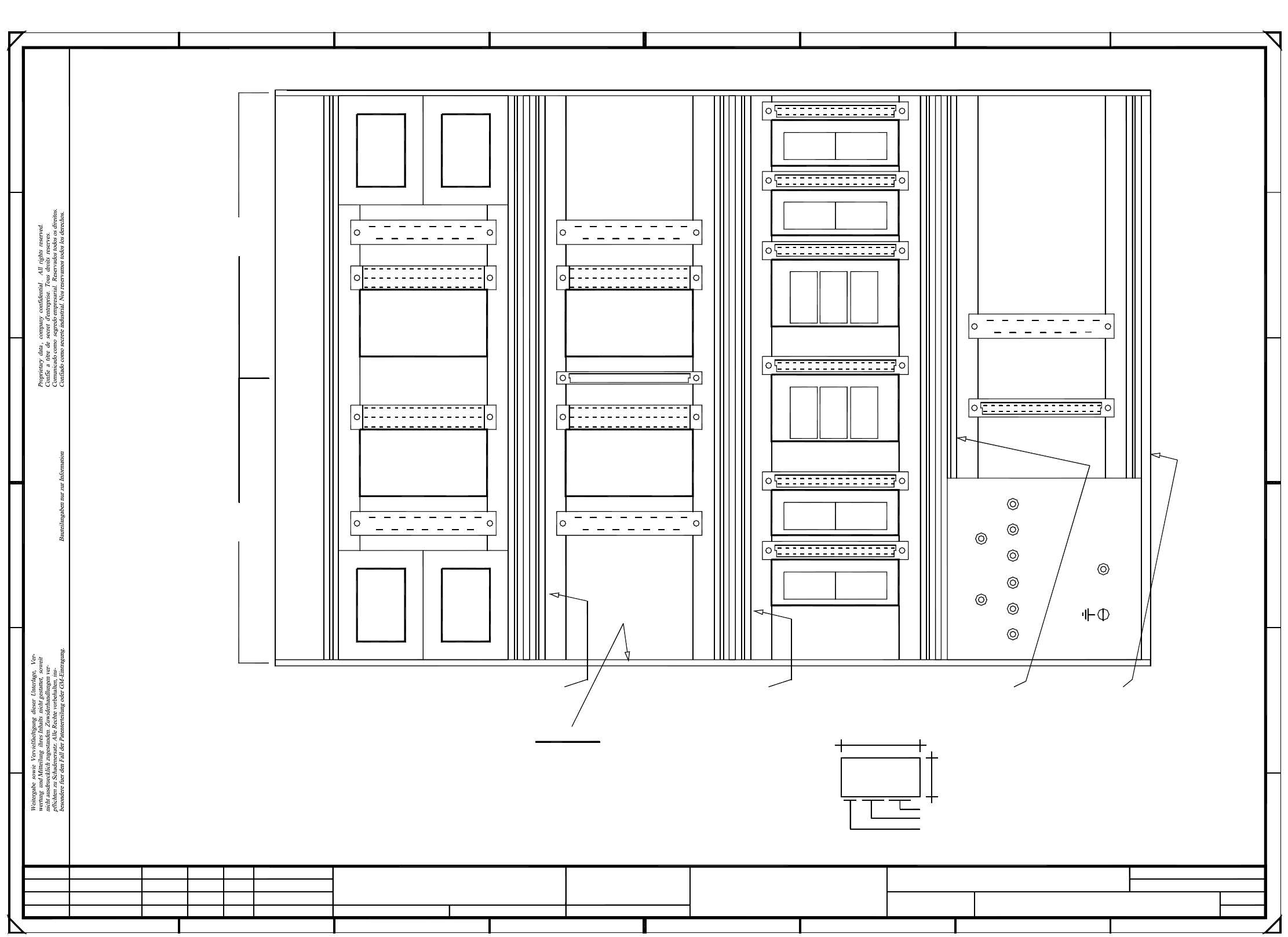
3 SIPLACE 80S-20 Circuit Diagrams 78
00321693-030101TD3 80S20 servo unit, basic module, viewed from the front (Sh. 2 of 3)
L7/L8
L5/L6
X8
3
1
F F
32 41
8
004
24V
1L+
7
567
C
001
8
GND
X12
A26
A25
L3/L4
E
003
56
B
006
40
00321693 /03
L1/L2
002 005
D
C
B
A
2
X73
X7
009
6L+
008
18
2
A
2L+/5L+
A27
A19
A24
SIEMENS PLEA
AA-BBBB-CCCC
A20
A21
A22
7L+
5V
E
34
X13
D
12V
007
2L+
Deu
Deu
03
01
01
30.09.98
30.09.98
30.09.98
30.09.98
Haas
#
00321693-030101TD3
X72
A18
A23
X11
PL EA1 E
Deu
Date
Check.
Author
Creat. byCreat. f.Orig.NameModified DateStatus Stand.
Sh.
Sheet
SMD Placement System SIPLACE 80S20
Document status
Product status
Function status
Date (year/month/day) acc. to SN 01007
Manufacturer/location acc. to SN 37040
Series number
80S20 servo unit, basic module
(viewed from the front)
as seen from the front:
Installation sequence of the chokes
L6 behind L5;
L8 behind L7;
L2 behind L1;
L4 behind L3;
Please note:
Fit inscription labels A-C
acc. to drawing 00323329
Inscription label AInscription label BInscription label CInscription label D
* Please note
On the inside (flush with the front plate)
apply the following labels:
A: identification label, assembly inscription acc. to VA-F-510-001
Font size 2.5mm
Material Scotchal 3698-E (color Al RAL 9006)
B: inspection label Identification: testing engineer, month, year
A28 fan unit
Gantry I Gantry II
Power supply unit
Ballast circuit
Z-axis II
DP1-axis II
Star II
Star I
Z-axis I
DP1-axis I
Dynamic brake X I
X-axis I
Anti-crash board
X-axis II
Dynamic brake X IIDynamik brake Y II
Y-axis II
Y-axis I
Dynamik brake Y I
=
SIEMENS AG
+
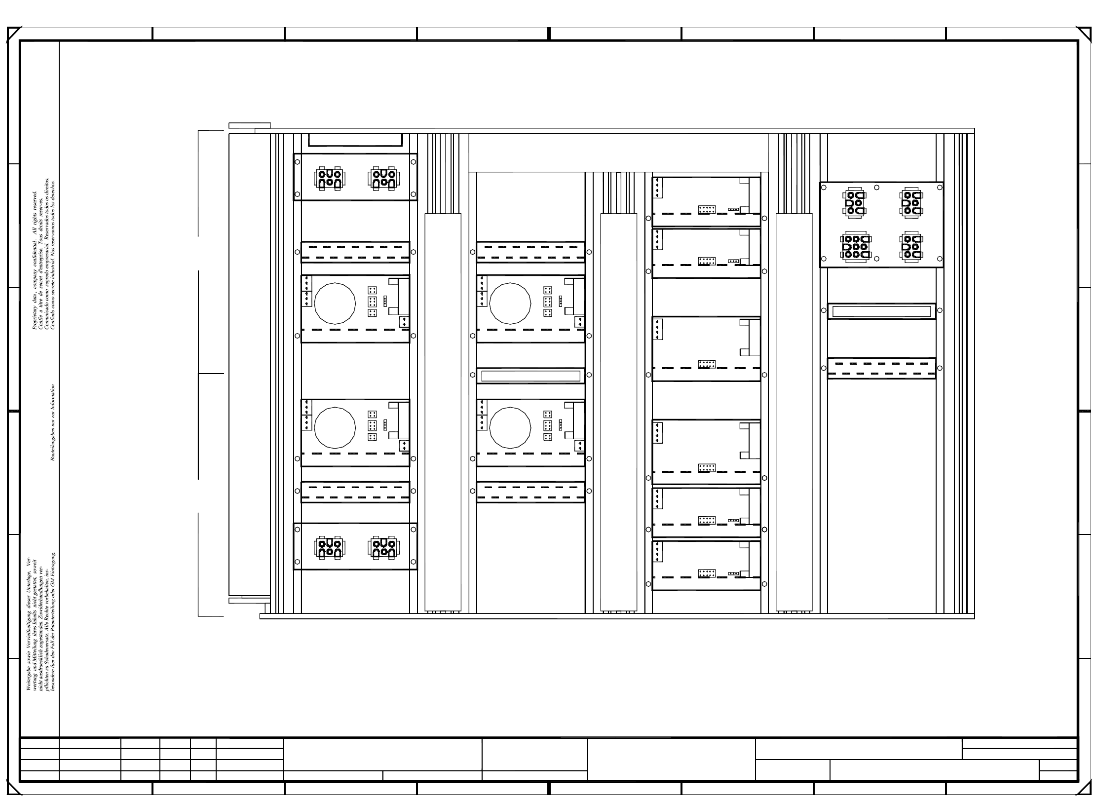
3 SIPLACE 80S-20 Circuit Diagrams 79
00321693-030101TD3 80S20 servo unit, basic module, viewed from the back (Sh. 3 of 3)
PL EA1 E
30.09.98
30.09.98
00321693-030101TD3#
Haas
30.09.98
30.09.98
X4
A18
51 56
X7
(II)
(I)
X80
X70
(II)
38
X2
X12
X13
292110
X72
19
X1 (vm)
X7
X2
32
X6
X5X3X4
A23
38
X11
X1 (va)
X7
X2
X6
X5X3
60x30 l=300mm
63 68
X71
510
X73
X6
X5
(I)
39
X1 (vc)
X3
A22
X4
X2
55
A
C
23
F
E
B
X14
X4
X8
45
60x30 l=300mm
7
C
X3
2315 63
X1 (vp)
71
X1 (vo)
X3
A27
X4
X2
X1 (vd)
X3
A21
X4
60x30 l=300mm
A20
X4
X2X2X2
2
A
B
19
X1 (vn)
X7
X2
32
X6
X5X3X4
A24
X3
X6
X5X3X4
A19
51 56
A25
6 8
D
X1 (vb)
X7
X2
D
X3
3
3
X1 (vr)
34
X2
X1 (vf)
X3
A26
X4
E
F
30x30 l=250mm
X4
01
01
03
Deu
Deu
Deu
1 7865
1
Date
Check.
Author
Creat. byCreat. f.Orig.NameModified DateStatus Stand.
Sh.
Sheet
SMD Placement System SIPLACE 80S20
Document status
Product status
Function status
80S20 servo unit, basic module
(viewed from the back)
Gantry II Gantry I
A28 fan unit
Cable channel 003
Cable channel 004
Cable channel 002
Cable channel 001
Ballast circuit
Power supply unit
DP1-axis II
Z-axis II
Star II
Star I
Z-axis I
DP1-axis I
Dynamic X brake
X-axis II
X-axis
Anti-crash board
X-axis I
X-axis
Dynamic X brake
Y-motor
Y-motor
Dynamic Y brake
Y-axis II
Y-axis
Y-axis I
Y-axis
Dynamic Y brake
X-motor
X-motor
=
SIEMENS AG
+